
Intelligent electric vehicle trajectory tracking and motion control method

A smart electric vehicle, trajectory tracking technology, applied in the direction of electric vehicles, control drives, control devices, etc., can solve the problems of reducing vehicle driving safety, control conflicts, and inability to guarantee vehicles

Active Publication Date: 2020-11-06
JILIN UNIV
View PDF24 Cites 22 Cited by
  • Summary
  • Abstract
  • Description
  • Claims
  • Application Information

AI Technical Summary

Problems solved by technology

[0004] 1. Trajectory tracking controllers and motion controllers at this stage can better track the desired trajectory to ensure the stability of the vehicle under certain conditions, but there are few studies on the factors affecting the adhesion conditions and vehicle speed. It is difficult to ensure the stability and ride comfort of the vehicle on complex road surfaces
[0005] 2. Most of the current research on trajectory tracking and dynamics control of smart vehicles adopts a separate design of the trajectory tracking controller and the vehicle yaw stability controller, and the two controllers have a common actuator (such as steering motor and drive motor) , will cause control conflicts, especially in complex road conditions or high-speed driving, which will reduce the driving safety of the vehicle
[0006] 3. Trajectory tracking control and vehicle dynamics control at the present stage are mainly based on model-based controller design, which is highly dependent on the environment and parameter selection, that is, when the environment changes suddenly, it cannot adapt well to the new state conditions. Tracking
However, in real life, it cannot be guaranteed that the vehicle can simply work in simple or complex working conditions. Obviously, the trajectory tracking controller at this stage cannot meet the vehicle trajectory tracking under all working conditions.

Method used


Image

  • Intelligent electric vehicle trajectory tracking and motion control method
  • Intelligent electric vehicle trajectory tracking and motion control method
  • Intelligent electric vehicle trajectory tracking and motion control method

Examples


Embodiment Construction

[0092] In order to describe the technical content, structural features, and realization goals of the present invention in detail, the present invention will be fully explained below in conjunction with the accompanying drawings.

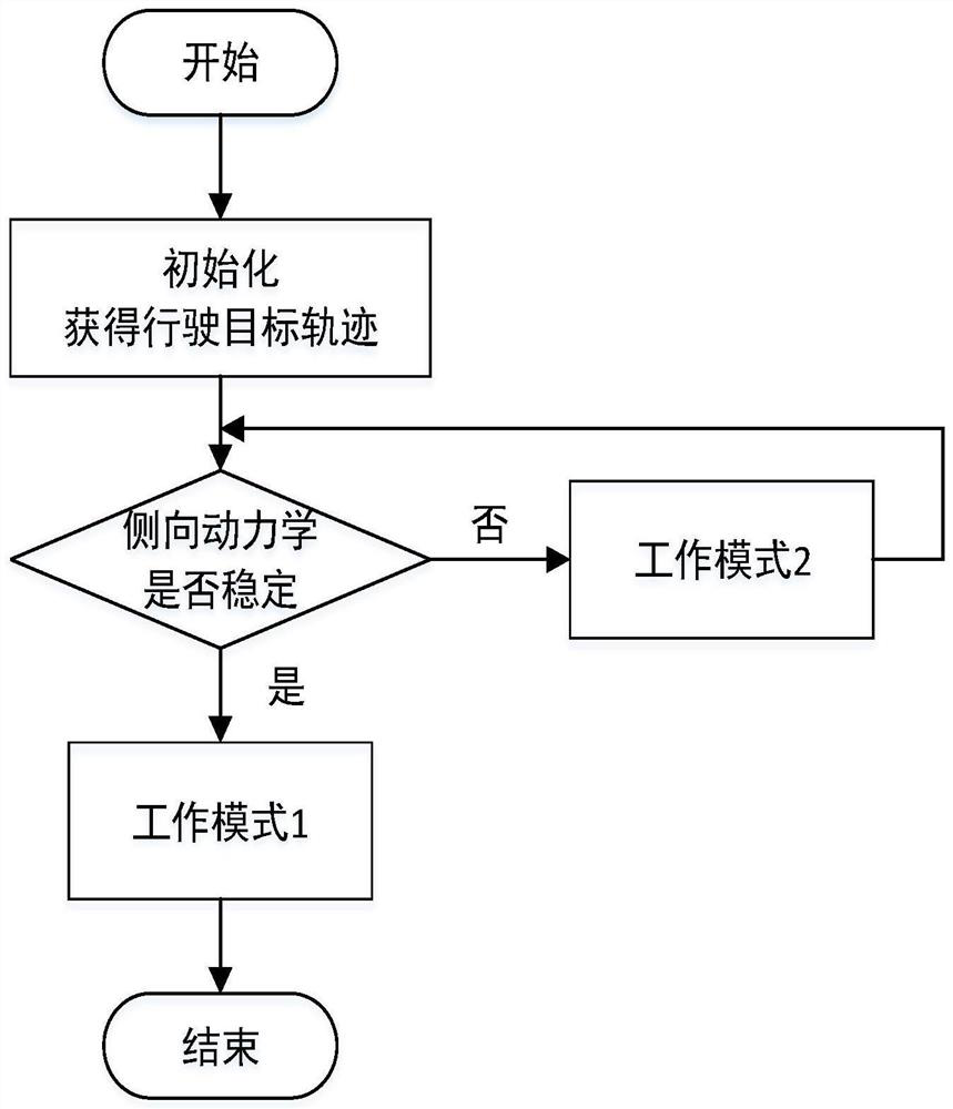
[0093] The overall working frame of the present invention is to adopt the idea of ​​switching control, such as figure 1 As shown, a smart electric vehicle trajectory tracking and motion control method follows the following steps:

[0094] Step 1: According to the given target trajectory and current road conditions, judge whether the vehicle can work within the lateral stability range; if it works within the stable range, perform step 2; if it exceeds the lateral stability range, perform step 3;

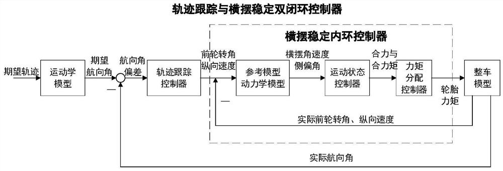
[0095] Step 2: Execute working mode 1, and use the vehicle trajectory tracking and yaw stability dual closed-loop controller to perform vehicle trajectory tracking and stability control, such as figure 2 Shown: According to the expected driving trajectory ...


PUM


Abstract

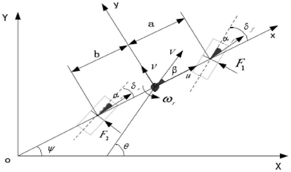
The invention discloses an intelligent electric vehicle trajectory tracking and motion control method which comprises the following steps: judging whether a vehicle can work in a lateral stable rangeor not according to a given target trajectory and a current road condition; if the vehicle works in the stable area, executing the step 2; if the lateral stability range is exceeded, executing the step 3; 2, executing a working mode 1, and performing vehicle trajectory tracking and stability control by adopting vehicle trajectory tracking and yawing stability double closed-loop control: calculating an expected course angle of a vehicle according to an expected driving trajectory and a vehicle kinematics model; establishing a three-degree-of-freedom vehicle dynamic model, designing a trajectorytracking controller, inputting the difference between the expected course angle of the vehicle and the course angle of the previous moment into the trajectory tracking controller, and solving to obtain a front wheel rotation angle and a longitudinal speed; designing a yaw stability controller by adopting a model predictive control algorithm and then carrying out moment distribution; and 3, executing a working mode 2, and carrying out drifting control on vehicle trajectory tracking.

Description

technical field [0001] The invention relates to a control method belonging to the field of optimal control of the chassis of a four-wheel hub-driven electric vehicle. More specifically, the invention relates to a smart vehicle trajectory tracking and stability control method based on switching control, involving the kinematics of the vehicle With dynamic control, it can improve the handling, stability and comfort of the vehicle. Background technique [0002] With the society's demand for intelligent, low-carbon and lightweight vehicles, the development of smart electric vehicles has become an important way to improve vehicle safety, reduce environmental pollution and save energy. Traditional active safety control systems have been unable to meet the current complex traffic conditions. environment, so it is particularly important for the development of the electronic control system of smart electric vehicles. The traditional control method mainly considers separately the tra...

Claims


Application Information

Patent Timeline
IPC IPC(8): B60L15/20B60W50/00
CPCB60L15/20B60W50/00B60L2240/423B60L2240/32B60L2240/64B60L2240/12B60L2240/24B60W2050/0034Y02T10/72
Inventor 赵海艳刘晓斌赵津杨刘万陈伟轩
Owner JILIN UNIV
Learn More