
ATP fluorescent microfluidic chip, bioluminescence continuous detection system and detection method

A microfluidic chip and detection system technology, applied in chemiluminescence/bioluminescence, chemical instruments and methods, measurement devices, etc., can solve the problems of small reaction chamber space and insufficient reaction, and achieve the effect of large storage volume

Active Publication Date: 2021-07-13
XI AN JIAOTONG UNIV
View PDF8 Cites 0 Cited by
  • Summary
  • Abstract
  • Description
  • Claims
  • Application Information

AI Technical Summary

Problems solved by technology

[0005] Chinese patent CN201811556016.5 proposes an ATP fluorescent microfluidic chip used in a centrifuge. The ATP fluorescent microfluidic chip consists of a chip base and a chip cover. The chip base is disc-shaped, and the disc-shaped There are multiple detection units around the center point of the chip substrate. The detection needs to be centrifuged at variable speeds multiple times. After the solution is completely reacted, it can be placed in a professional fluorescence detection equipment to detect the fluorescence intensity. Only a single result of the final reaction can be achieved. Measurement, and the reaction chamber is set on the substrate, the reaction chamber space is small, resulting in insufficient reaction

Method used


Image

  • ATP fluorescent microfluidic chip, bioluminescence continuous detection system and detection method
  • ATP fluorescent microfluidic chip, bioluminescence continuous detection system and detection method
  • ATP fluorescent microfluidic chip, bioluminescence continuous detection system and detection method

Examples


Embodiment Construction

[0037] In order to make the purpose, technical solutions and advantages of the embodiments of the present invention clearer, the technical solutions of the present invention will be clearly and completely described below in conjunction with the accompanying drawings. Obviously, the described embodiments are part of the embodiments of the present invention, not all of them. the embodiment. Based on the embodiments of the present invention, all other embodiments obtained by persons of ordinary skill in the art without making creative efforts belong to the protection scope of the present invention.

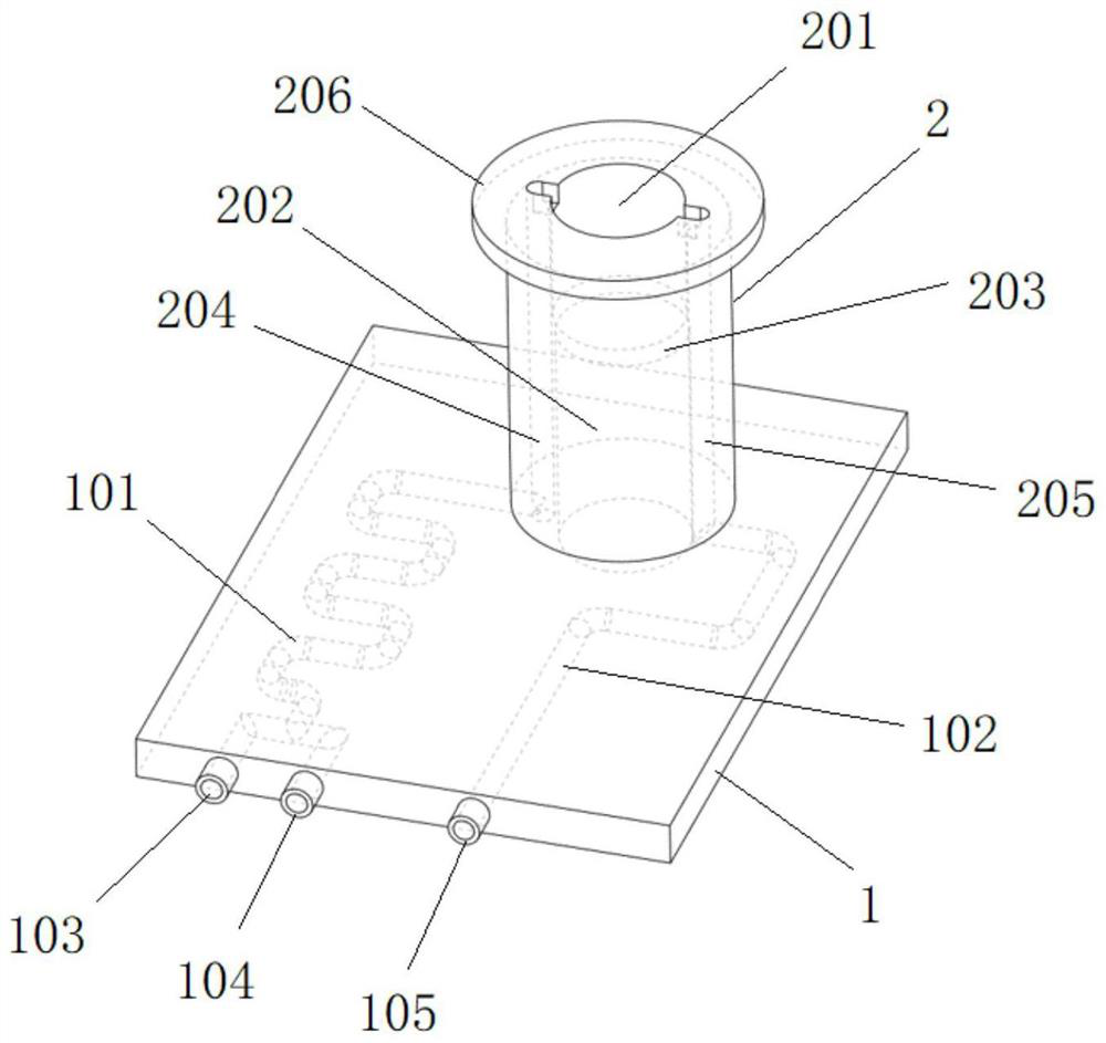
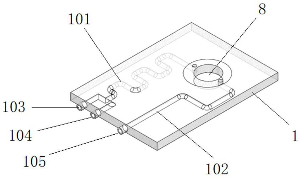
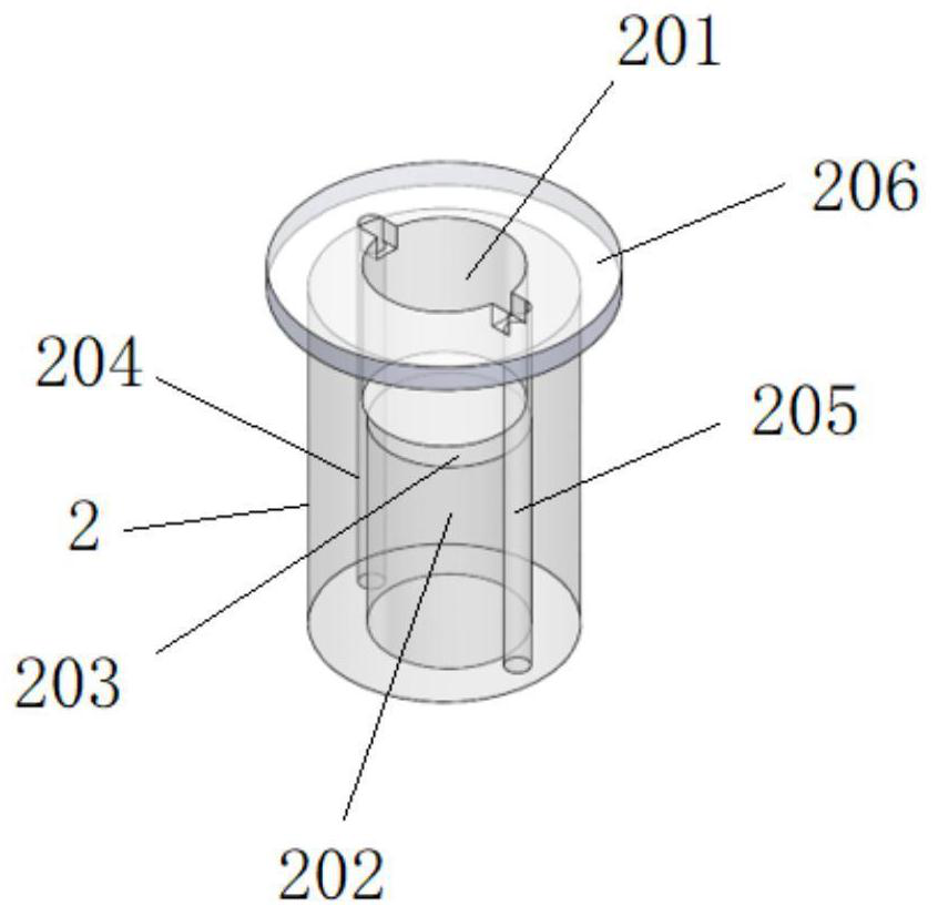
[0038] As a specific embodiment of the present invention, in combination with figure 1 , figure 2 As shown in and 3, an ATP fluorescent microfluidic chip includes a microfluidic chip substrate 1 and a platform 2 arranged on the microfluidic chip substrate 1, the microfluidic chip substrate 1 is a cuboid, and the platform 2 is a The cylinder, the microfluidic chip substrate 1 and t...


PUM


Abstract

The invention discloses an ATP fluorescent microfluidic chip, a bioluminescent continuous detection system and a detection method, an ATP fluorescent microfluidic chip, which includes a microfluidic chip substrate and a platform arranged on the microfluidic chip substrate, and a microfluidic chip substrate. A first micro-channel and a second micro-channel are opened on the substrate of the control chip, one end of the first micro-channel is used to input sample liquid and luciferase solution, and one end of the second micro-channel is used to discharge waste after reaction. liquid; the top of the table body is provided with a reaction pool, and the bottom of the table body is provided with a housing chamber, which is used to place photoelectric sensors, and a light-transmitting interlayer is arranged between the reaction pool and the housing chamber; the side wall of the table body is provided with There are a third micro-channel and a fourth micro-channel, one end of the third micro-channel communicates with the other end of the first micro-channel, one end of the fourth micro-channel communicates with the other end of the second micro-channel, and the second micro-channel communicates with the other end of the second micro-channel. The other ends of the third micro-channel and the fourth micro-channel communicate with the top of the reaction pool. The invention can continuously detect the biological reaction process.

Description

technical field [0001] The invention belongs to the technical field of microfluidic chips and bioluminescent detection, and in particular relates to an ATP fluorescent microfluidic chip, a bioluminescent continuous detection system and a detection method. Background technique [0002] Microorganisms are a substance that widely exists in nature, and their existence has a huge effect on the life activities of organisms. But from a human point of view, the existence of some pathogenic colony microorganisms will also have a negative impact on food safety and environmental monitoring, so the detection of these microorganisms is of great significance. [0003] In some traditional biological measurements, we often pay attention to the final biological reaction results and ignore the specific conditions in the biological reaction process. Although the final result can be used to know the product of the reaction, it cannot help to understand the biological real-time response events, ...

Claims


Application Information

Patent Timeline
Patent Type & Authority Patents(China)
IPC IPC(8): B01L3/00B01J19/00G01N21/76
CPCB01J19/0053B01J19/0093B01L3/5027B01L2200/10B01L2300/0861G01N21/763
Inventor 彭年才李治鹏胡飞张航郭晓牛
Owner XI AN JIAOTONG UNIV
Learn More