
Positioning device for gearbox shift fork shaft

A technology of positioning device and shift fork shaft, which is applied in the direction of measuring device, optical device, workpiece clamping device, etc., can solve the problems that the clamping method cannot adapt to the shift fork shaft, is not suitable for continuous operation, and the installation of workpiece is complicated. To achieve the effect of being conducive to continuous detection, realizing continuous detection and improving efficiency

Active Publication Date: 2022-04-12
IKD CO LTD
View PDF16 Cites 0 Cited by
  • Summary
  • Abstract
  • Description
  • Claims
  • Application Information

AI Technical Summary

Problems solved by technology

However, the installation of the workpiece in the technical solutions disclosed by these two patents is complicated, and it is not suitable for continuous operation; and the clamping method cannot be adapted to the fork shaft for detecting the horizontal fork hole.

Method used


Image

  • Positioning device for gearbox shift fork shaft
  • Positioning device for gearbox shift fork shaft
  • Positioning device for gearbox shift fork shaft

Examples


Embodiment Construction

[0039] Preferred embodiments of the present invention will be described in detail below with reference to the accompanying drawings. Those skilled in the art will appreciate that these descriptions are descriptive and exemplary only, and should not be interpreted as limiting the protection scope of the present invention.

[0040] It should be noted that similar reference numerals denote similar items in the following figures, therefore, once an item is defined in one figure, it may not be further defined and explained in subsequent figures.

[0041] In the description of the present invention, it should be noted that the orientation or positional relationship indicated by the terms "upper", "lower", "inner", "outer" etc. is based on the orientation or positional relationship shown in the drawings, or is the The usual orientation or positional relationship of the invention product in use is only for the convenience of describing the present invention and simplifying the descrip...


PUM


Abstract

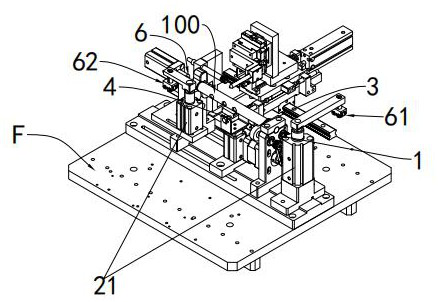
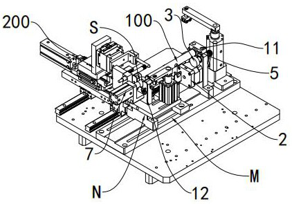
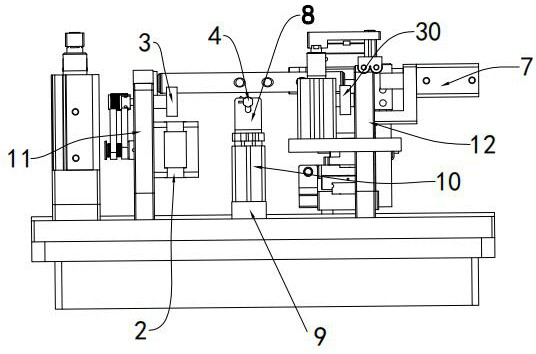
The invention discloses a positioning device for a shift fork shaft of a gearbox, which comprises a support seat for resting the shift fork shaft, and the shift fork shaft can rotate around its axis on the support seat; The motor and the roller group in contact with the shaft surface of the shift fork shaft, the motor drives the roller group to drive the shift fork shaft to rotate; a detection sensor with a fixed position is used to detect whether the shift fork hole of the shift fork shaft is at the preset orientation position. When the fork shaft rotates, when the detection sensor detects that the fork hole of the fork shaft is in a preset orientation, the motor stops rotating so that the fork shaft stops rotating; a positioning component includes a fixed limiting wall and a movable top One end face of the shift fork shaft is pressed against the limiting wall, and the other end face of the shift fork shaft is pressed tightly by the top contact at the stop position.

Description

technical field [0001] The invention relates to a clamping mechanism, in particular to a positioning device for a transmission fork shaft. Background technique [0002] The shift fork shaft of the gearbox has a rod-shaped structure, and several shift fork holes are arranged axially at intervals on its center line. Since the position of the fork hole is related to the realization of its function, the processing accuracy of the fork hole is very high, so a full inspection is required after processing to ensure product quality. [0003] In order to improve the detection efficiency, automatic assembly line operations are usually used, so a positioning device that can accurately assemble the shift fork shaft along a certain direction and position is required. And because of the continuous operation of the assembly line, it is more necessary for the positioning device to realize automatic positioning while positioning. [0004] The crankshaft eccentric positioning machine with a...

Claims


Application Information

Patent Timeline
Patent Type & Authority Patents(China)
IPC IPC(8): B25B11/00G01B11/00
CPCB25B11/00G01B11/00
Inventor 叶经纬唐楗喜
Owner IKD CO LTD
Learn More