
Self-deflection oil filtering device for oil-containing waste gas treatment

An oil filter device and waste gas treatment technology, which is applied in the fields of dispersed particle filtration, dispersed particle separation, chemical instruments and methods, etc., can solve the problems of few purchasing channels, low output, and damage to filtration equipment, so as to reduce insufficient oil filtration, The effect of prolonging the service life and speeding up the oil filtration efficiency

Inactive Publication Date: 2020-11-06
刘宝军
View PDF1 Cites 3 Cited by
  • Summary
  • Abstract
  • Description
  • Claims
  • Application Information

AI Technical Summary

Problems solved by technology

However, the walnut shells used in this utility model are agricultural and sideline products, and its output is small, and the purchase channels are few, and the supply volume and output are affected, so it has little application value in the specific implementation process.
And walnut shells are used as the packing layer. When the oil absorption of the packing layer reaches saturation, the packing layer needs to be replaced. In this process, the cost of production materials and labor costs are relatively large, and it is not suitable for large-scale promotion.
[0004] The oil contained in the exhaust gas is easy to cause great damage to the filter equipment due to its viscous liquid characteristics. Therefore, when the oil is treated, it is generally treated with artificial water or some simple equipment for adsorption treatment, which is inefficient and also It will cause waste of water resources, and the adsorption effect on oil pollution is poor. Often there will still be a large amount of unadsorbed oil pollution in the exhaust gas, which will easily block the filter equipment in the next process and even cause damage.

Method used


Image

  • Self-deflection oil filtering device for oil-containing waste gas treatment
  • Self-deflection oil filtering device for oil-containing waste gas treatment
  • Self-deflection oil filtering device for oil-containing waste gas treatment

Examples


Embodiment 1

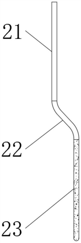
[0040] see Figure 1-2 , a self-deflecting oil filter device for oily waste gas treatment, comprising an oil filter plate 1, the lower end of the oil filter plate 1 is fixedly connected with a plurality of evenly distributed segmented oil filter fiber rods 2, and the oil filter plate 1 is provided with a plurality of Ventilation holes 3 are evenly distributed, and the segmental oil filter fiber rods 2 and air holes 3 are alternately distributed. The segmental oil filter fiber rods 2 include upper fixed oil filter fiber rods 21 and middle deflection transition rods distributed up and down in sequence. 22 and down moving oil filter fiber rod 23, and are connected with each other.

[0041] Both the upper fixed oil filter fiber rod 21 and the lower movable oil filter fiber rod 23 are made of oil-absorbing material, the middle deflection transition rod 22 is made of elastic material, and the oil absorption of the lower movable oil filter fiber rod 23 is better than that of the uppe...


PUM


Abstract

The invention discloses a self-deflection oil filtering device for oil-containing waste gas treatment. The invention belongs to the technical field of oily waste gas treatment. Densely distributed segmental oil filtering fiber rods can be arranged at the lower end of an oil filtering plate; the characteristic that the upper and lower parts have deflection distances is utilized; an oil absorption gap between the adjacent segmental oil filtering fiber rods is eliminated; the contact sufficiency is improved in a space range; therefore, the oil filtering effect and efficiency of the oil-containingwaste gas are improved; after the segmental oil filtering fiber rods adsorb, saturate and gain weight; a lower movable oil filtering fiber rod on the segmental oil filtering fiber rods forces a middle deflection transition rod to generate self-deflection action due to the reason that the weight is increased; a pre-embedded magnetic pressure liquid release ball is used for carrying out extrusion action based on the magnetic repulsion effect, so that an emulsifier for oil stains is released and is guided to the emulsification-promoting disintegration microsphere, and the permeation of the emulsifier and the emulsification of the oil stains are accelerated by utilizing the characteristic that the emulsification-promoting disintegration microsphere fiercely releases gas and vibrates when meeting water.

Description

technical field [0001] The invention relates to the technical field of oily waste gas treatment, and more specifically relates to a self-deflecting oil filter device for oily waste gas treatment. Background technique [0002] Oily waste gas is often produced in industrial production, such as the existing printing and dyeing, petrochemical, coating and other fields. During the processing, high concentrations of organic waste gas such as smoke, oil stains, etc. will be emitted, such as gasoline, naphtha and benzene, etc. , not only waste resources, but also pollute the environment, and leave a major fire or explosion hazard. For the treatment of oily waste gas, the industry often converts the oil and gas into a liquid state before processing it. [0003] For example, in the patent application document whose patent application number is "200620077362.1", a kind of degreasing device for oily waste gas is disclosed. An oily waste gas inlet is arranged under the packing layer, a...

Claims


Application Information

Patent Timeline
IPC IPC(8): B01D46/10B01D46/28
CPCB01D46/10B01D46/28
Inventor 刘宝军
Owner 刘宝军
Learn More