
Functionally gradient crash barrier and construction method thereof

A technology of anti-collision guardrails and functional gradients, which is applied to bridge parts, erection/assembly of bridges, bridge materials, etc., can solve the problems of large impact force, easy failure, and high maintenance cost for drivers and passengers, so as to ensure construction quality and construction Efficiency, superior impact resistance effect

Pending Publication Date: 2020-11-03
HUNAN UNIV
View PDF0 Cites 0 Cited by
  • Summary
  • Abstract
  • Description
  • Claims
  • Application Information

AI Technical Summary

Problems solved by technology

However, studies have shown that although the traditional reinforced concrete rigid guardrail has the advantage of strong impact resistance, it has the disadvantages of large impact force on the driver and passengers, and poor vehicle guidance, resulting in a large number of secondary collision accidents, casualties
Corresponding grades of steel structure guardrails have good energy consumption and better orientation than rigid concrete guardrails, but they have the disadvantages of high initial cost, easy failure due to steel corrosion problems, and high maintenance costs. Intrusion into the vehicle body, causing the danger of personal injury or death

Method used


Image

  • Functionally gradient crash barrier and construction method thereof
  • Functionally gradient crash barrier and construction method thereof
  • Functionally gradient crash barrier and construction method thereof

Examples


Embodiment 1

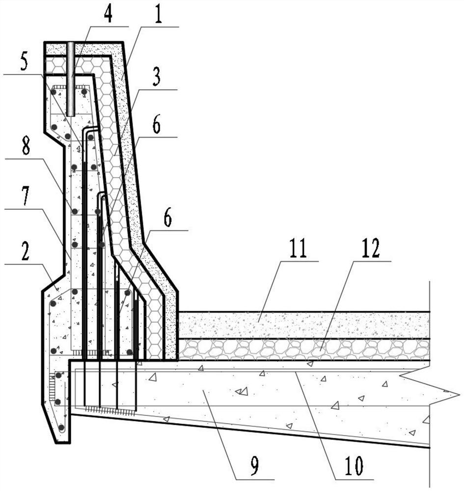
[0044] Such as figure 1 As shown, the functional gradient crash barrier of this embodiment includes a base 2, an energy dissipation layer 3, a UHPC panel 1 and an energy dissipation connector 4, and the energy dissipation layer 3 is arranged between the base 2 and the UHPC panel 1, and the base The seat 2, the energy dissipation layer 3 and the UHPC panel 1 are connected as a whole through the energy dissipation connector 4, and there are one or more energy dissipation connectors 4 (only one is shown in the figure).

[0045] In this embodiment, the guardrail is installed on the cantilever arm 9 of the beam body, and the steel bar 6 required for the connection with the base 2 is reserved on the cantilever arm 9 of the beam body, and the steel bar in the beam body is pre-embedded in the cantilever arm 9 of the beam body.

[0046] In this embodiment, the energy-dissipating connector 4 runs through the UHPC panel 1 and the energy-dissipating layer 3 , and extends into the base 2 ,...

Embodiment 2

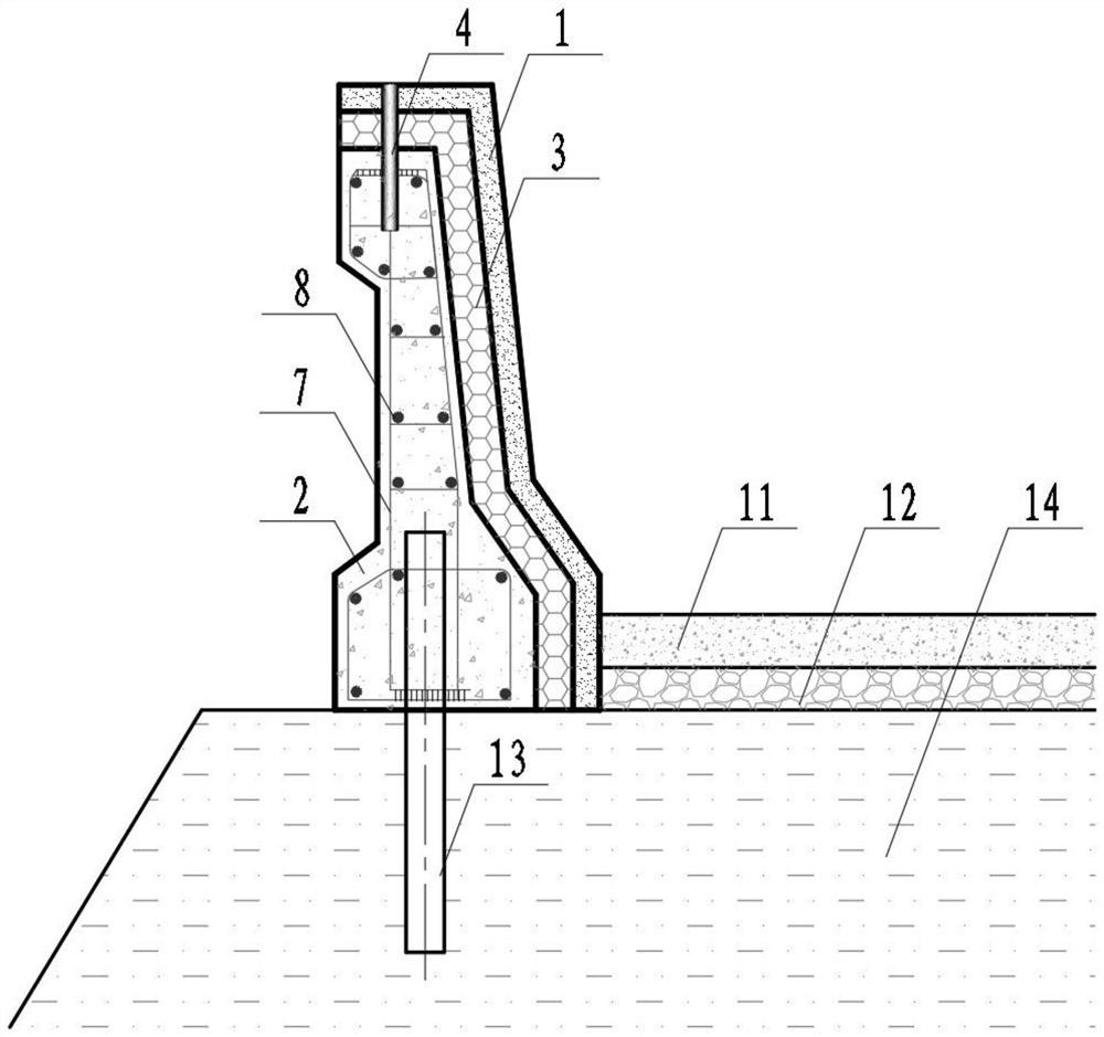
[0058] Such as figure 2 As shown, the functional gradient crash barrier of this embodiment includes a base 2, an energy dissipation layer 3, a UHPC panel 1 and an energy dissipation connector 4, and the energy dissipation layer 3 is arranged between the base 2 and the UHPC panel 1, and the base The seat 2, the energy dissipation layer 3 and the UHPC panel 1 are connected as a whole through the energy dissipation connector 4, and there are one or more energy dissipation connectors 4 (only one is shown in the figure).

[0059] In this embodiment, the guardrail is installed on the road of the soil roadbed 14, and steel pipe piles 13 required for connection with the base 2 are reserved on the soil roadbed 14.

[0060] In this embodiment, the energy-dissipating connector 4 runs through the UHPC panel 1 and the energy-dissipating layer 3 , and extends into the base 2 , and the position of the energy-dissipating connector 4 is set on the top of the guardrail.

[0061] In this embod...

Embodiment 3

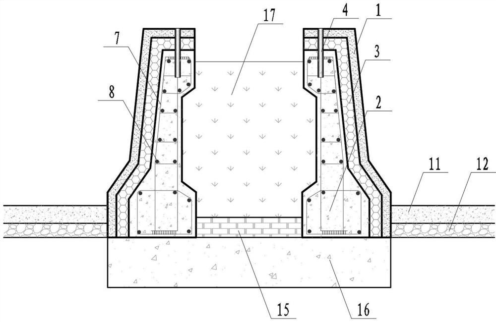
[0072] Such as image 3 As shown, the functional gradient crash barrier of this embodiment includes a base 2, an energy dissipation layer 3, a UHPC panel 1 and an energy dissipation connector 4, and the energy dissipation layer 3 is arranged between the base 2 and the UHPC panel 1, and the base The seat 2, the energy dissipation layer 3 and the UHPC panel 1 are connected as a whole through the energy dissipation connector 4, and there are one or more energy dissipation connectors 4 (only one is shown in the figure).

[0073] In this embodiment, the guardrail is installed on the separate central divider.

[0074] In this embodiment, the energy-dissipating connector 4 runs through the UHPC panel 1 and the energy-dissipating layer 3 , and extends into the base 2 , and the position of the energy-dissipating connector 4 is set on the top of the guardrail.

[0075] In this embodiment, the energy dissipation connector 4 is a metal rod or a metal tube.

[0076] In this embodiment, t...


PUM


Abstract

The invention discloses a functionally gradient crash barrier, and the crash barrier comprises a base, an energy dissipation layer and a UHPC panel, wherein the energy dissipation layer is arranged between the base and the UHPC panel. The invention further provides a construction method of the functionally gradient crash barrier. The construction method comprises the following steps: S1, prefabricating the reinforced concrete base, the UHPC panel and the energy dissipation layer, when the reinforced concrete base, the UHPC panel and the energy dissipation layer are prefabricated, pipelines forinstalling the energy dissipation connecting pieces are synchronously reserved; S2, installing the base on a bridge or a road; S3, installing an energy dissipation layer and a UHPC panel on the base,inserting the energy dissipation connecting pieces, and completing the construction of the functionally gradient crash barrier. The functionally gradient anti-collision guardrail has the advantages of being good in guidance quality, capable of reducing accident consequences, good in durability, low in manufacturing cost, short in construction period, easy and convenient to maintain and replace and the like, has a great use value and good economic benefits, and has wide application prospects.

Description

technical field [0001] The invention belongs to the field of auxiliary facilities for roads and bridges, and in particular relates to an anti-collision guardrail and a construction method thereof. Background technique [0002] Freeway traffic accidents are closely related to the geometric characteristics of the road and traffic ancillary facilities, and the guardrail on the freeway is an important factor affecting traffic safety. Statistics show that in road traffic accidents, traffic accidents occurring on expressways account for 55%, and 30% of them are vehicles contacting (collision, scratching, etc.) with expressway guardrails or directly driving out of the road. On October 28, 2018, a bus from the Second Yangtze River Bridge in Wanzhou District, Chongqing, broke through the bridge guardrail and fell into the Yangtze River, causing all 15 people on the bus to die or lose contact. On June 13, 2020, a tank truck exploded on the expressway in Wenling City, Zhejiang Provinc...

Claims


Application Information

Patent Timeline
Patent Type & Authority Applications(China)
IPC IPC(8): E01F15/02E01D19/10F16F15/02E01D21/00E01D101/24
CPCE01F15/02E01D19/103F16F15/02E01D21/00E01D2101/24
Inventor 樊伟孙文彪谢瑞洪邵旭东
Owner HUNAN UNIV
Learn More