
Five-axis machine tool error measurement method based on ball rod instrument

A technology of error measurement and ballbar, which is applied in the direction of measuring/indicating equipment, metal processing machinery parts, metal processing equipment, etc., can solve the problems of failing to measure the errors of linear axes and rotary axes at the same time, and achieve good practicability and measurement High precision and improved measurement efficiency

Inactive Publication Date: 2020-11-03
TIANJIN UNIV
View PDF4 Cites 4 Cited by
  • Summary
  • Abstract
  • Description
  • Claims
  • Application Information

AI Technical Summary

Problems solved by technology

[0004] Existing error measurement methods fail to measure both linear axis and rotary axis errors

Method used


Image

  • Five-axis machine tool error measurement method based on ball rod instrument
  • Five-axis machine tool error measurement method based on ball rod instrument
  • Five-axis machine tool error measurement method based on ball rod instrument

Examples


Embodiment Construction

[0047] The present invention will be further described below in conjunction with the accompanying drawings and specific embodiments.

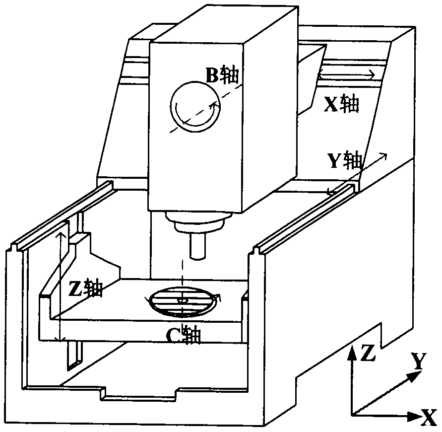
[0048] attached figure 1 Shown is a schematic structural diagram of a five-axis machine tool, and the method of the present invention is described by taking the machine tool as an example.

[0049] In step 1, the geometric error model of the five-axis machine tool is established based on the spiral theory, including steps:

[0050] Step 1.1, in the method of the present invention, only involve machine tool Z-axis and B-axis motion, so machine tool kinematics model is as follows:

[0051]

[0052] in and Indicates the initial position of the tool and the workpiece relative to the machine tool coordinate system under ideal conditions, represent the B-axis screw and the Z-axis screw, respectively.

[0053] Step 1.2. Introduce geometric errors into the machine tool model by multiplying the error screw to the left. Taking the Z axis as...


PUM


Abstract

The invention discloses a five-axis machine tool error measurement method based on a ball rod instrument. The method comprises the following steps of constructing a machine tool error model based on aspiral theory; establishing a mathematical model of constant-speed linkage of a Z axis and a B axis of a machine tool so as to ensure that data acquired by the ball rod instrument is synchronous withactual motion in the measurement process, and calculating machine tool codes based on the mathematical model; measuring machine tool errors. and performing error decoupling on the data measured by the ball rod instrument, so that geometric errors in a two-axis linkage measurement process can be solved. According to the method, simultaneous measurement of the geometric errors of the Z axis and theB axis of the machine tool is realized, so that the measurement efficiency is greatly improved.

Description

technical field [0001] The invention relates to the technical field of error measurement of five-axis machine tools, in particular to a method for measuring errors of five-axis machine tools based on a ballbar. [0002] technical background [0003] Compared with the three-axis machine tool, the structure of the five-axis machine tool is more complex, and the two rotary axes introduce additional geometric errors to it. At the same time, there is also error coupling between the linear axis and the rotary axis, which greatly affects the accuracy of the machine tool. Therefore, in order to ensure the accuracy of the machine tool, it is necessary to measure the geometric error of the linear axis and the rotary axis. [0004] Existing error measurement methods fail to measure linear axis and rotary axis errors simultaneously. Therefore, a method for efficiently measuring the errors of the linear axis and the rotary axis is proposed, so as to realize the simultaneous measurement o...

Claims


Application Information

Patent Timeline
Patent Type & Authority Applications(China)
IPC IPC(8): B23Q17/00
CPCB23Q17/00
Inventor 张福民姚思涵蒋晓耕郑继辉曲兴华
Owner TIANJIN UNIV
Learn More