a cable tie

A lap joint and cable technology, which is applied in the field of power cables, can solve problems such as high-voltage cables are prone to leakage, narrow application range, and cable aging, and achieve the effects of saving time for matching lap joint specifications, wide application range, and preventing moisture.

Active Publication Date: 2021-08-27
国网河南省电力公司柘城县供电公司
View PDF11 Cites 0 Cited by
  • Summary
  • Abstract
  • Description
  • Claims
  • Application Information

AI Technical Summary

Problems solved by technology

[0002] The cable is the bridge between the power supply equipment and the electrical equipment, which plays the role of transmitting electric energy, and the high-voltage cable is a kind of power cable, which is mostly used in power transmission and distribution. After the high-voltage cable is laid, in order to make it a continuous Lines, each section of the line must be connected as a whole, so the cables need to be lapped. Before the cables are lapped, the insulation protection sheet at the corresponding position of the original cable will be removed, so that part of the cable is exposed and locked through the cable lap joint. Lap joints are used to prevent the cables from being exposed. The existing cable lap joints are only suitable for cables of this specification due to their fixed specifications. The aging of high-voltage cables is prone to leakage, even explosion and fire

Method used


Image

  • a cable tie
  • a cable tie
  • a cable tie

Examples


Embodiment 1

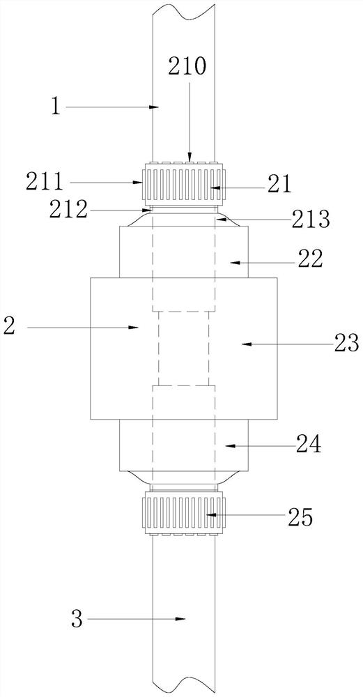
[0034] See Figure 1-3 The present invention provides a technical solution for a cable lap: there is a structure including one cable 1, a lap device 2, a cable 3, and the first cable 1 is connected to the second cable 3, the No. 1 A lap 1 is provided with a lap 1 and the second cable 3, and the lap device 2 is connected to the No. 1 cable 1, the second cable 3.

[0035] The lap device 2 includes a 1st sealing fastening mechanism 21, a 1st mounting mechanism 22, a moisture-proof casing 23, a 2nd mounting mechanism 24, a sealing fastening mechanism 25, and the moisture-proof casing 23 ends The mounting mechanism 22 is connected to the No. 1 seal fastening mechanism 21, and the other end is connected to the second mounting mechanism 24 and the second sealing fastening mechanism 25, the first seal fastening mechanism 21, No. 1 mounting mechanism 22 and No. 1 Cable 1 is connected, the secondary mounting mechanism 24, and the second sealing fastening mechanism 25 are connected to the sec...

Embodiment 2

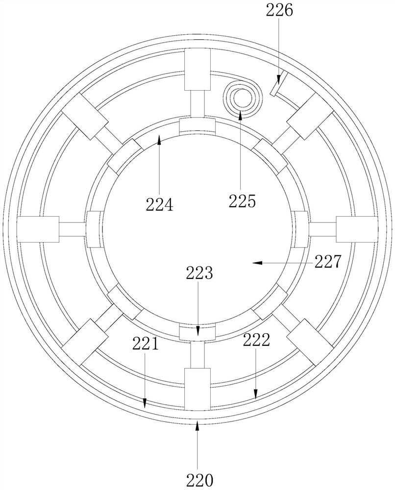
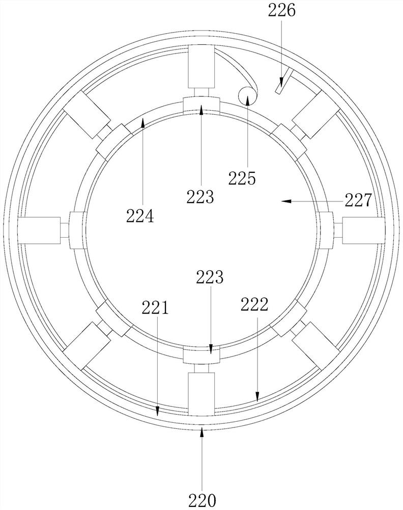
[0043] See Figure 1-7 The present invention provides a technical solution for a cable lap: there is a structure including one cable 1, a lap device 2, a cable 3, and the first cable 1 is connected to the second cable 3, the No. 1 A lap 1 is provided with a lap 1 and the second cable 3, and the lap device 2 is connected to the No. 1 cable 1, the second cable 3.

[0044] The lap device 2 includes a 1st sealing fastening mechanism 21, a 1st mounting mechanism 22, a moisture-proof casing 23, a 2nd mounting mechanism 24, a sealing fastening mechanism 25, and the moisture-proof casing 23 ends The mounting mechanism 22 is connected to the No. 1 seal fastening mechanism 21, and the other end is connected to the second mounting mechanism 24 and the second sealing fastening mechanism 25, the first seal fastening mechanism 21, No. 1 mounting mechanism 22 and No. 1 Cable 1 is connected, the secondary mounting mechanism 24, and the second sealing fastening mechanism 25 are connected to the sec...


PUM


Abstract

The invention discloses a cable lapping device, the structure of which comprises a No. 1 cable, a lap joint device, and a No. 2 cable. device, the lapping device is connected with No. 1 cable and No. 2 cable. Compared with the prior art, the beneficial effect of the present invention is that: the present invention uses No. 1 sealing fastening mechanism, No. 1 installation mechanism, moisture-proof sleeve, and No. 2 The combined setting of the installation mechanism and the No. 2 sealing and fastening mechanism can be applied to cables of different specifications, and has a wide range of applications. It can fully protect the cable lap joints, prevent cables from being damp and short-circuited, reduce cable aging, and avoid cable failures and leakage , to prevent the cable explosion and fire.

Description

Technical field [0001] The present invention relates to the field of power cable technology, and is specifically a cable lap. Background technique [0002] The cable is a bridge between the power supply equipment and the electrical equipment, and the high voltage cable is one of the power cable. It is used in power transmission and distribution. After the high-voltage cable is laid, in order to make it a continuous The line, each line must be connected to a whole, so it is necessary to lap the cable. Before the cable is lap, the insulated protective sheet corresponding to the original cable will be removed, so that some of the cable is exposed, lock through the cable tape Take the connection to prevent the cable from exposure, the existing cable lap can only be applied to the cable, which can only be applied to the cable, the scope of application is narrow, and only the cable slap cannot be fully protected, which is easy to make the cable aging. The high-voltage cable aging is pr...

Claims


Application Information

Patent Timeline
Patent Type & Authority Patents(China)
IPC IPC(8): H02G15/18H02G15/013
CPCH02G15/013H02G15/18
Inventor 谢志强
Owner 国网河南省电力公司柘城县供电公司
Why Eureka
Try Eureka