Cable lap joint device

A lap joint and cable technology, applied in the field of power cables, can solve the problems of high voltage cables prone to leakage, narrow application range, cable aging, etc.

Active Publication Date: 2020-10-30
国网河南省电力公司柘城县供电公司
View PDF11 Cites 2 Cited by
  • Summary
  • Abstract
  • Description
  • Claims
  • Application Information

AI Technical Summary

Problems solved by technology

[0002] The cable is the bridge between the power supply equipment and the electrical equipment, which plays the role of transmitting electric energy, and the high-voltage cable is a kind of power cable, which is mostly used in power transmission and distribution. After the high-voltage cable is laid, in order to make it a continuous Lines, each section of the line must be connected as a whole, so the cables need to be lapped. Before the cables are lapped, the insulation protection sheet at the corresponding position of the original cable will be removed, so that part of the cable is exposed and locked through the cable lap joint. Lap joints are used to prevent the cables from being exposed. The existing cable lap joints are only suitable for cables of this specification due to their fixed specifications. The aging of high-voltage cables is prone to leakage, even explosion and fire

Method used


Image

  • Cable lap joint device
  • Cable lap joint device
  • Cable lap joint device

Examples


Embodiment 1

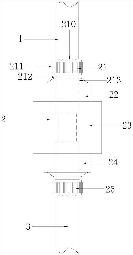
[0034] see Figure 1-3 , the present invention provides a technical solution of a cable splicer: its structure includes a No. 1 cable 1, a lapping device 2, and a No. 2 cable 3, and the No. A lapping device 2 is provided at the junction of the cable 1 and the No. 2 cable 3 , and the lapping device 2 is connected to the No. 1 cable 1 and the No. 2 cable 3 .

[0035] The overlapping device 2 includes a No. 1 sealing and fastening mechanism 21, a No. 1 installation mechanism 22, a moisture-proof casing 23, a No. 2 installation mechanism 24, and a No. 2 sealing and fastening mechanism 25. One end of the moisture-proof casing 23 passes through the No. The installation mechanism 22 is connected to the No. 1 sealing and fastening mechanism 21, and the other end is connected to the No. 2 sealing and fastening mechanism 25 through the No. 2 installation mechanism 24. The No. 1 sealing and fastening mechanism 21, the No. 1 installation mechanism 22 and the No. The cable 1 is connected,...

Embodiment 2

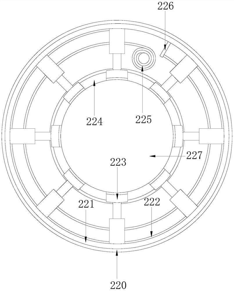
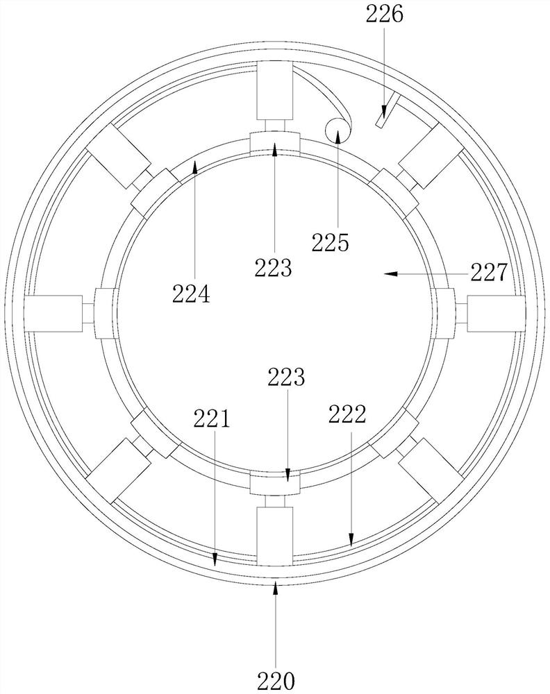
[0043] see Figure 1-7 , the present invention provides a technical solution of a cable splicer: its structure includes a No. 1 cable 1, a lapping device 2, and a No. 2 cable 3, and the No. A lapping device 2 is provided at the junction of the cable 1 and the No. 2 cable 3 , and the lapping device 2 is connected to the No. 1 cable 1 and the No. 2 cable 3 .

[0044] The overlapping device 2 includes a No. 1 sealing and fastening mechanism 21, a No. 1 installation mechanism 22, a moisture-proof casing 23, a No. 2 installation mechanism 24, and a No. 2 sealing and fastening mechanism 25. One end of the moisture-proof casing 23 passes through the No. The installation mechanism 22 is connected to the No. 1 sealing and fastening mechanism 21, and the other end is connected to the No. 2 sealing and fastening mechanism 25 through the No. 2 installation mechanism 24. The No. 1 sealing and fastening mechanism 21, the No. 1 installation mechanism 22 and the No. The cable 1 is connected,...


PUM


Abstract

The invention discloses a cable lap joint device. The device structurally comprises a first cable, a lapping device and a second cable, the first cable is connected with the second cable; the lappingdevice is arranged at the joint of the first cable and the second cable, and connected with the first cable and the second cable. Compared with the prior art, the cable lap joint device has the advantages that a first sealing and fastening mechanism, a first mounting mechanism, a damp-proof sleeve, a second mounting mechanism and a second sealing and fastening mechanism are arranged in a combinedmode; the device is suitable for cables of different specifications, is wide in application range, can comprehensively protect the lap joint of the cables, prevents the cables from being affected withdamp and short-circuited, reduces aging of the cables, avoids electric leakage caused by faults of the cables, and prevents the cables from exploding and catching fire.

Description

technical field [0001] The invention relates to the technical field of power cables, in particular to a cable lap. Background technique [0002] The cable is the bridge between the power supply equipment and the electrical equipment, which plays the role of transmitting electric energy, and the high-voltage cable is a kind of power cable, which is mostly used in power transmission and distribution. After the high-voltage cable is laid, in order to make it a continuous Lines, each section of the line must be connected as a whole, so the cables need to be lapped. Before the cables are lapped, the insulation protection sheet at the corresponding position of the original cable will be removed, so that part of the cable is exposed and locked through the cable lap joint. Lap joints are used to prevent the cables from being exposed. The existing cable lap joints can only be used for cables of this specification due to their fixed specifications. The scope of application is narrow, ...

Claims


Application Information

Patent Timeline
Patent Type & Authority Applications(China)
IPC IPC(8): H02G15/18H02G15/013
CPCH02G15/013H02G15/18
Inventor 谢志强
Owner 国网河南省电力公司柘城县供电公司
Why Eureka
Try Eureka