R-test precision ball head detection device and calibration method thereof

A detection device and calibration method technology, applied in the direction of measuring devices, instruments, etc., can solve the problems of positioning error, processing error, detection and calibration error, etc.

Active Publication Date: 2020-10-30
SICHUAN UNIV
View PDF6 Cites 7 Cited by
  • Summary
  • Abstract
  • Description
  • Claims
  • Application Information

AI Technical Summary

Problems solved by technology

Nowadays, the R-test precision ball head detection device is commonly used to detect and calibrate the processing machine tools. The R-test precision ball head detection device includes an adjustable slide table, R-test ball head and R-test ball head mounting seat , the mounting seat is composed of a solid circular column-shaped bracket. After placing the R-test ball head on the top of the mounting seat, the data is collected to perform error detection on the processing machine tool. However, the R-test precision ball head was not detected before the error detection of the processing machine tool. The device is calibrated, and there is a positioning error between the R-test precision ball head detection device and the processing machine tool. There will be certain errors in the subsequent detection and calibration of the processing machine tool, which will cause processing errors.

Method used


Image

  • R-test precision ball head detection device and calibration method thereof
  • R-test precision ball head detection device and calibration method thereof
  • R-test precision ball head detection device and calibration method thereof

Examples


Embodiment 1

[0031] This embodiment provides a mounting base 100, the mounting base 100 is fixed on the five-dimensional manual sliding table, and the corresponding sensor and R-test ball head 400 are matched and installed, and then equipped with the corresponding software algorithm to realize the multi-axis linkage accuracy detection of the machine tool and calibration.

[0032] The mounting seat 100 described in this embodiment is provided with a mounting surface 101, a reference surface A102, a reference surface B103 and a fixing surface 104, and its structure is as follows figure 1 shown. There are three installation surfaces 101, and the three installation surfaces 101 are evenly distributed on the same ring with the axis of the installation seat 100 as the center of the circle, and the installation surfaces 101 are all inclined to the center of the circle, and the distance between the three installation surfaces 101 and the horizontal plane The included angles between them are equal...

Embodiment 2

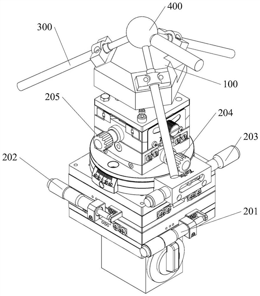
[0036] This embodiment provides an R-test detector, which includes a five-dimensional manual slide table, a displacement sensor 300, an R-test ball head 400 and the mounting seat 100 provided in Embodiment 1. Its structure is as follows figure 2 shown. The five-dimensional manual sliding table adopts the high-precision sliding table series developed by Zhuoli Hanguang. The main material is made of 2024 aluminum alloy material, and its surface is oxidized black, with high strength, good wear resistance and beautiful appearance. The five-dimensional manual slide table described in this embodiment includes two mutually perpendicular linear slide table A202 and linear slide table B201, a rotary slide table 203, and two mutually perpendicular swing slide table A204 and swing slide table B205; The linear slide table A202, the linear slide table B201, the rotary slide table 203, the swing slide table A204 and the swing slide table B205 are arranged in sequence from bottom to top, an...

Embodiment 3

[0038] This embodiment provides a method for calibrating the R-test precision ball head detection device, which is used to calibrate the positioning error between the R-test precision ball head detection device and the processing machine tool. The R-test precision ball head detection device The calibration method includes the following steps:

[0039](1) The R-test precision ball detection device described in embodiment 2 is installed on the worktable of the processing machine tool through the magnetic suction base, and the R-test precision ball detection device is adjusted during installation so that the reference plane A102 is in line with the processing machine tool The coordinates XOY are parallel, and the reference plane B103 is parallel to the coordinates XOZ of the processing machine tool. At this time, the parallelism is roughly parallel through the naked eye observation of the staff, and the precise parallelism required by the processing has not been realized. The prec...


PUM


Abstract

The invention discloses an R-test precision ball head detection device, which comprises a five-dimensional manual sliding table, an R-test ball head and a mounting seat, wherein the mounting seat is provided with three mounting surfaces for mounting sensors, and a reference surface A and a reference surface B for calibration, the mounting seat is fixedly mounted on the top surface of the five-dimensional manual sliding table, displacement sensors are fixedly mounted on the mounting surfaces of the mounting seat, the extension lines of the three displacement sensors are orthogonal to a point P,and the center of sphere of the R-test ball head is located at the point P. According to the invention, by arranging the mounting seat with the reference surface A and the reference surface B, afterthe sensor is mounted, the detection device can be calibrated, so that the positioning error when the R-test detection device is mounted and positioned on the workbench of the processing machine toolis reduced, the detection result of the volume error is accurate and reliable, and the direction vector of the axis of the R-test sensor can be directly obtained so as to simplify the conversion method of the subsequent volume error in each coordinate system and provide convenience for geometric error identification.

Description

technical field [0001] The invention relates to the technical field of detection devices for precision machining machine tools, in particular to an R-test precision ball head detection device and a calibration method thereof. Background technique [0002] Multi-axis linkage CNC machining machine tools are widely used in aviation, aerospace, automobiles, ships and other fields because of improving the machining accuracy, quality and efficiency of free-form surfaces in space. With the advancement of science and technology, various manufacturing industries have an increasing demand for parts processing and manufacturing accuracy, and higher requirements are also placed on the processing accuracy of processing machine tools. [0003] In view of the complexity of the structural accuracy analysis of the current machine tool and the urgent need to improve the precision design level of the processing machine tool, it is necessary to establish an accuracy analysis model and develop n...

Claims


Application Information

Patent Timeline
Patent Type & Authority Applications(China)
IPC IPC(8): G01B21/00
CPCG01B21/00G01B21/045
Inventor 殷鸣蒲耀洲谭朝元张志王玲谢罗锋殷国富
Owner SICHUAN UNIV
Why Eureka
Try Eureka