Spring push rod mechanism, rapid connection device and anti-loose method

A spring push rod and rod head technology, applied in the direction of pivot connection, connecting rod, shaft installation, etc., can solve problems such as loosening and detachment, bending deformation of mandrel and joint bearing, potential safety hazards, etc., to avoid loosening and detachment, avoid bending Effects of deformation and improvement of industrial efficiency

Pending Publication Date: 2020-10-30
JIANGSU CHANGLONG PETROCHEM EQUIP
View PDF0 Cites 2 Cited by
  • Summary
  • Abstract
  • Description
  • Claims
  • Application Information

AI Technical Summary

Problems solved by technology

[0005] One of the purposes of the present invention is to solve the problems in the prior art that the mandrels may be loosened due to rotation and threaded connection, causing the mandrels and joint bearings to bend and deform, which poses a safety hazard

Method used


Image

  • Spring push rod mechanism, rapid connection device and anti-loose method
  • Spring push rod mechanism, rapid connection device and anti-loose method
  • Spring push rod mechanism, rapid connection device and anti-loose method

Examples


Embodiment 1

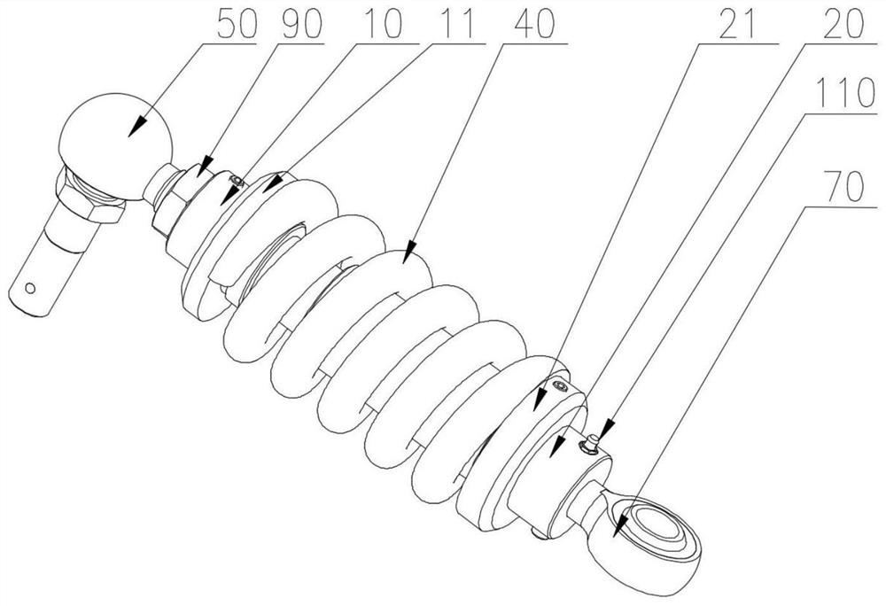
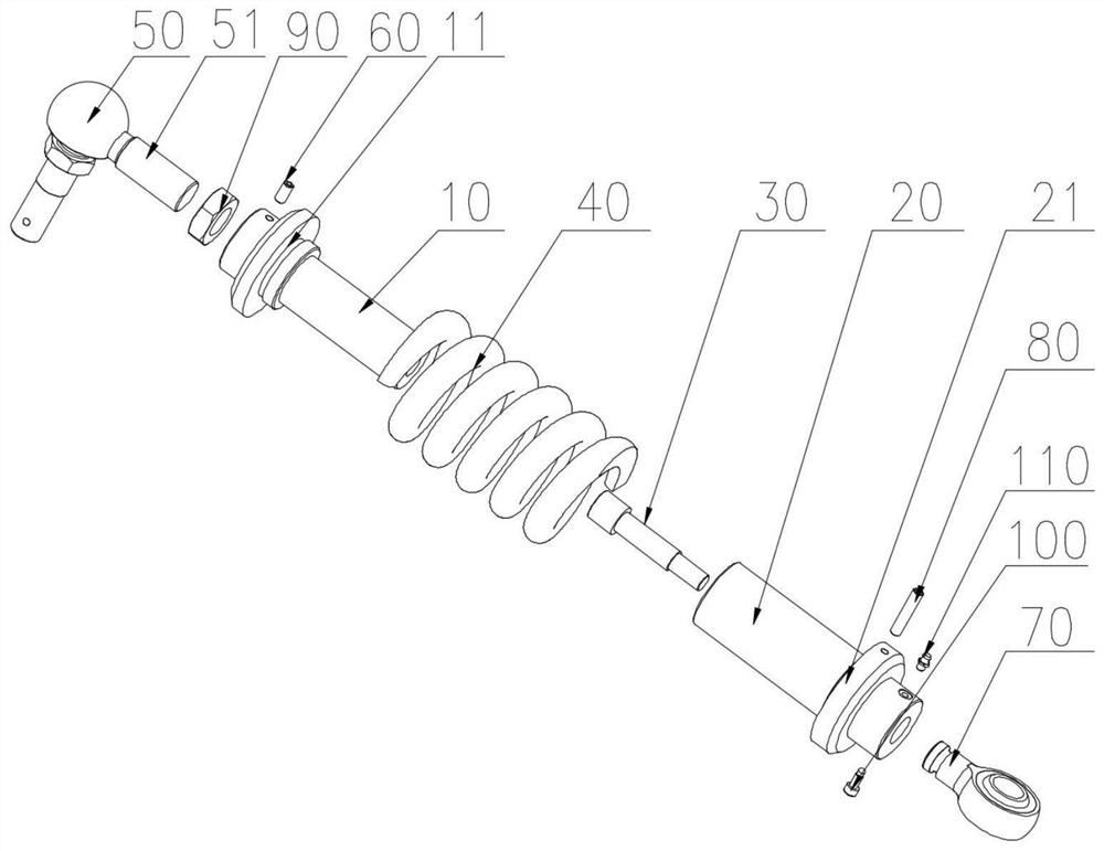
[0052] A spring 40 push rod mechanism, wherein, as figure 1 , 2 As shown, it includes: a first mandrel 10 , a second mandrel 20 , a spring 40 , a limit rod 30 , a ball joint bearing 50 , and a joint bearing 70 .

[0053] The first mandrel 10 has a first flange 11 located on the outer surface of the first mandrel 10 . The second mandrel 20 is telescopically connected with the first mandrel 10, and one end of the first mandrel 10 extends into the cavity of the second mandrel 20, the second mandrel 20 has a second flange 21, and the second flange 21 is located on the outer surface of the second mandrel 20 .

[0054] The spring 40 is disposed between the first mandrel 10 and the second mandrel 20 , and both ends of the spring 40 abut against the first flange 11 and the second flange 21 . The first mandrel 10 also has an accommodation chamber 12 and a through hole 13 , the through hole 13 passes through the accommodation chamber 12 and the cavity, and the diameter of the through...

Embodiment 2

[0082] A quick connection device, which includes the spring 40 push rod mechanism of any one of the technical solutions in the first embodiment above.


PUM


Abstract

The invention discloses a spring push rod mechanism and a rapid connection device and relates to the technical field of marine fluid loading and unloading special-purpose equipment. The spring push rod mechanism comprises a first core shaft, a second core shaft, a spring, a position-limiting rod, a ball head joint bearing and a joint bearing, wherein the position-limiting rod is connected betweenthe first core shaft and the second core shaft to make the position-limiting rod form concave-convex coordination with the first core shaft and make the position-limiting rod form fixed connection with the second core shaft at the same time, no matter how the first core shaft and the second core shaft move relative to each other, the position-limiting rod can always clamp the first core shaft, andloose separation between the first core shaft and the second core shaft is avoided. Compared with adoption of position limiting by a fan-shaped light groove, the structural strength of the position-limiting rod is stronger than that of the fan-shaped light groove, and the position-limiting rod can realize a better position-limiting effect; and by means of the second core shaft and the joint bearing in rotating connection, reduction of the rotation force and angle of the second core shaft is facilitated, the loose separation phenomenon occurring at the threaded connection positions between thefirst core shaft and the ball head joint bearing is improved, and bending deformation of the core shafts and the joint bearing is avoided.

Description

technical field [0001] The invention relates to the technical field of special equipment for loading and unloading marine fluids, in particular to a spring push rod mechanism and a quick connection device. Background technique [0002] The marine loading and unloading arm is a special equipment used to realize docking with ships to load and unload liquids on the port wharf. The quick connection device QCDC is an important part for the quick docking of the loading arm and the ship, and the spring push rod mechanism in the quick connection device QCDC is an important part for transmission and compression during the docking process between the jaws of the connection device and the ship flange. [0003] The existing spring push rod mechanism is connected by two separate mandrels through fan-shaped optical grooves staggered by 90° to realize the position limit, but the mandrel of the spring push rod mechanism is frequently compressed and released during the spring. The mandrels ...

Claims


Application Information

Patent Timeline
IPC IPC(8): F16C7/06F16C11/06F16C23/04F16N1/00
CPCF16C7/06F16C11/0695F16C23/043F16N1/00F16C2226/62F16C2326/30F16C2326/58
Inventor 冯是公孟军金泽宇余圣武
Owner JIANGSU CHANGLONG PETROCHEM EQUIP
Why Eureka
Try Eureka