
Integrated energy-saving blast furnace blast dehumidification system

A blast furnace blasting and dehumidification technology, applied in blast furnaces, blast furnace details, blast furnace parts and other directions, can solve the problems of large dehumidifiers and high equipment costs, achieve obvious system energy saving, improve the level of cold energy utilization, and reduce system costs. The effect of resistance

Active Publication Date: 2020-10-30
HUATIAN ENG & TECH CORP MCC +1
View PDF7 Cites 2 Cited by
  • Summary
  • Abstract
  • Description
  • Claims
  • Application Information

AI Technical Summary

Problems solved by technology

This method causes the volume of the dehumidifier to be large, and the equipment cost is high

Method used


Image

  • Integrated energy-saving blast furnace blast dehumidification system
  • Integrated energy-saving blast furnace blast dehumidification system
  • Integrated energy-saving blast furnace blast dehumidification system

Examples


example 1

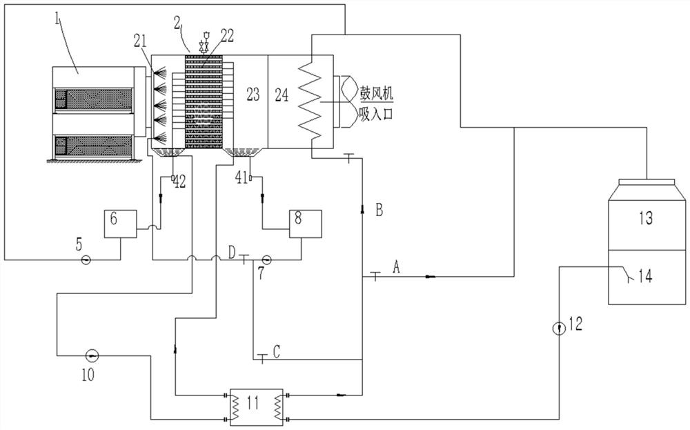
[0032] The conventional dehumidification process is as follows: the air enters the dehumidifier 2 through the filter 1 for dehumidification, and the dehumidified air is sent to the blast furnace blower after mechanical demisting; after the dehumidifier 2 imports chilled water to absorb the heat of the air, it passes through the chilled water pump 10 Send it to the evaporator of the refrigeration unit 11 for cooling, and then send the cooled chilled water to the dehumidifier 2 to form a cycle;

[0033] The refrigerant cooled by the cooling tower 13 enters the water pool 14, and the cooled refrigerant is sent to the condenser of the refrigeration unit 11 through the circulating water pump 12 to absorb the heat released by the cooling medium. to the cooling tower for cooling. The condensed water after the air passes through the dehumidifier 2 flows into the condensed water tank 8 through the first automatic drain device 41, is pressurized by the condensed water pump 7, and flows ...

example 2

[0035] Aiming at the loss of cold energy caused by the failure of the condensed water in Example 1 to directly recycle its cooling capacity, in Example 2, the condensed water in the condensed water tank 8 is sent into the spray chamber 21 through the condensed water pump 7, and the spray chamber 21 passes through The nozzle atomizes the condensed water into small droplets, and the SMD of the droplets is usually controlled below 100μm. The atomized water mist first contacts the air at the outlet of filter 1, which can pre-cool the air by 3-5°C, which is equivalent to 3% energy saving of the system ~5%. A part of the spray water falls directly to the lower sump, is collected by the second automatic drainage device 42, and then sent to the drainage tank 6. After passing through the drainage pump 5 and the outlet water of the air-water heat exchanger, it flows into the refrigerant return pipe together as a cooling tower replenishment.

example 3

[0037] The temperature of the refrigerant passing through the refrigerating unit 11 rises by 5°C, and the refrigerant enters the air-water heat exchanger 24 through the second pipeline B, which can heat the cooled saturated humid air by 3-10°C, and the refrigerant itself drops by 1-2°C. After the saturated humid air is heated by the air-water heat exchanger 24, not only can the mechanical water be removed, but also the temperature and dryness of the air entering the blower can be improved by heating up, so as to ensure the safety of the blower blades.


PUM


Abstract

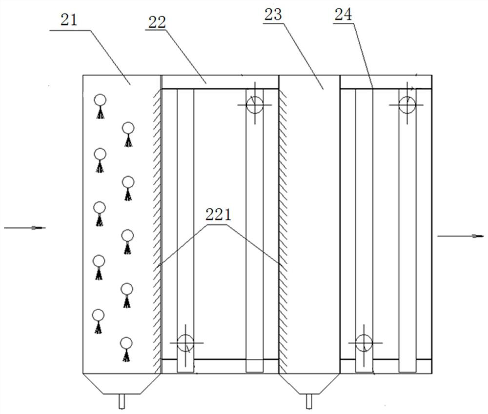
The invention discloses an integrated energy-saving blast furnace blast dehumidification system comprising a filter and a dehumidifier which are connected in sequence. The dehumidifier comprises a spraying room, a surface air cooler and a buffer room which are connected in sequence, and header tanks are arranged at the lower parts of the spraying room and the buffer room; the spraying room is provided with nozzles, and a water inlet of the surface air cooler communicates with a water outlet of a refrigeration unit; a water outlet of the surface air cooler communicates with a water inlet of therefrigeration unit, and a water tank is located below a cooling tower; a refrigerant inlet of the refrigeration unit communicates with a water outlet of the water tank, and a refrigerant outlet of the refrigeration unit communicates with the interior of the cooling tower through a first pipeline; the blast dehumidification system further comprises a first automatic drainage device, a condensate pump and a condensate water tank, and the first automatic drainage device communicates with the header tanks in the buffer room; and a water outlet of the condensate pump communicates with the nozzlesof the spraying room through fourth pipelines. According to the blast dehumidification system, through additional arrangement of a condensate water recycling system and a cooling air heating system, the cold energy utilization of the system is improved effectively, and the air dryness is improved; and the energy saving of the system is ensured, and the system safety is improved.

Description

technical field [0001] The invention relates to an integrated energy-saving blast furnace blast furnace dehumidification system. Its purpose is to reuse condensed water for the initial cooling of the air, and to demist and dry the cold air after heating and dehumidification by cooling circulating water, so as to realize energy saving of the dehumidification system. . Background technique [0002] Blast furnace blast dehumidification is to cool the air entering the blast furnace blower to realize the condensation of water vapor in the air and reduce the water content of the air entering the blast furnace. The humidity of the air entering the blast furnace can be relatively stable through dehumidification, which can effectively reduce the fluctuation of the combustion flame in the blast furnace and stabilize the production of the blast furnace. [0003] The conventional blast furnace blast dehumidification system uses a refrigeration mechanism to extract low-temperature froze...

Claims


Application Information

Patent Timeline
Patent Type & Authority Applications(China)
IPC IPC(8): C21B9/16
CPCC21B9/16
Inventor 余波王浩严厚华张学超王荣生张华钢杨智勇
Owner HUATIAN ENG & TECH CORP MCC
Learn More