Shot blasting polisher

A polishing machine and shot peening technology, which is applied in abrasive jet machine tools, used abrasive treatment devices, abrasives, etc., can solve the problems of troublesome pipeline cleaning process, large labor cost, low efficiency, etc.

Inactive Publication Date: 2020-10-30
滁州三界外工业设计有限公司
View PDF0 Cites 5 Cited by
  • Summary
  • Abstract
  • Description
  • Claims
  • Application Information

AI Technical Summary

Problems solved by technology

[0005] In order to make up for the deficiencies of the existing technology and solve the problems in the prior art that the pipeline cleaning process is cumbersome and inefficient and requires a lot of labor costs, a shot blasting machine proposed by the present invention

Method used


Image

  • Shot blasting polisher
  • Shot blasting polisher
  • Shot blasting polisher

Examples


Embodiment approach

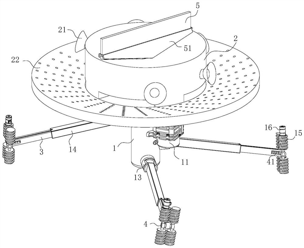
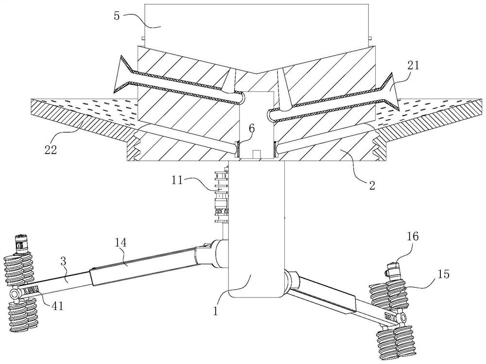
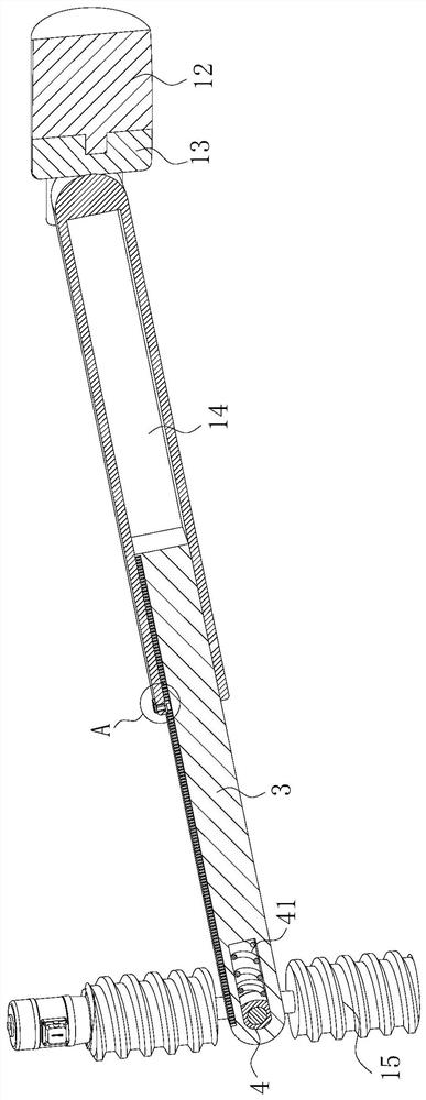
[0025] As an embodiment of the present invention, the rotating base 13 is provided with a first groove at the end away from the connecting base 12; the support rod 14 is connected in rotation in the first groove through a rotating shaft; the support rod 14 is away from the frame body 1 One end is provided with a sliding groove; the extension rod 3 is fixedly connected in the sliding groove; the upper surface of the extension rod 3 is provided with a limit groove; the inner wall of the limit groove is designed in a rack shape; the upper surface of the support rod 14 is provided with There is a first through slot; the limit block 31 is elastically connected by a spring in the first through slot; the limit block 31 is designed in a "ten" shape and the limit block 31 extends to the upper surface of the support rod 14; The bit block 31 is located at the upper surface of the support rod 14 and is connected with a rotating ring 32 for rotation; during work, due to the difference in th...


PUM


Abstract

The invention belongs to the technical field of pipeline cleaning, and particularly relates to a shot blasting polisher which comprises a frame body, a box body and an air compressor. The frame body is in cylindrical design; connecting seats which are uniformly distributed are fixedly connected to the side surface of the frame body; the number of the connecting seats is four, and the four connecting seats are all in different horizontal planes according to the design; the sides, far away from the frame body, of the connecting seats are rotatably connected with rotating seats through rotating shafts; the rotating seats are provided with supporting rods; the side, far away from the frame body, of each supporting rods is rotatably connected with rollers through a rotating shaft; the corresponding rollers are symmetrically arranged on the two sides of each supporting rod; the surfaces of the rollers are provided with threads; and the sides, away from the supporting rods, of the rollers arefixedly connected with electric motors. Since the supporting rods and the rollers which obliquely correspond to a pipe wall, the shot blasting polisher spirally ascends and descends in the pipeline,and further is matched with shot blasting pipes at different horizontal planes to perform rotary shot blasting impact, so that the pipeline is more evenly impacted by metal shots, and the shot blasting cleaning effect is enhanced.

Description

technical field [0001] The invention belongs to the technical field of pipeline cleaning, in particular to a shot blasting machine. Background technique [0002] In the prior art, during the long-term working process of the metal pipe exhaust device, the inner wall is easily attached with more dust and impurities. If it is not polished and cleaned during the long-term use, it will easily cause corrosion to the metal pipe. At the same time, when the impurities When the layer is thicker, it is easy to affect the exhaust effect. Since the exhaust pipes usually have different diameters and long lengths, when cleaning, they are often disassembled into multiple sections and then cleaned by beating. This cleaning method not only requires more manpower, but also has low cleaning efficiency. At the same time, because the exhaust pipe is affected by the hot gas for a long time, the dirt on the inner wall is relatively solid. When cleaning, it is easy to use too much force and cause da...

Claims


Application Information

Patent Timeline
Patent Type & Authority Applications(China)
IPC IPC(8): B24C1/08B24C3/32B24C9/00
CPCB24C1/08B24C3/325B24C9/00
Inventor 刘国庆李学海闫文霞
Owner 滁州三界外工业设计有限公司
Why Eureka
Try Eureka