Processing technology and processing system of LED ceramic substrates
A ceramic substrate and processing system technology, which is applied in the direction of metal processing equipment, manufacturing tools, grinding workpiece supports, etc., can solve the problems of ceramic substrates that cannot be ground
- Summary
- Abstract
- Description
- Claims
- Application Information
AI Technical Summary
Problems solved by technology
Method used
Image

Examples
specific Embodiment approach 1
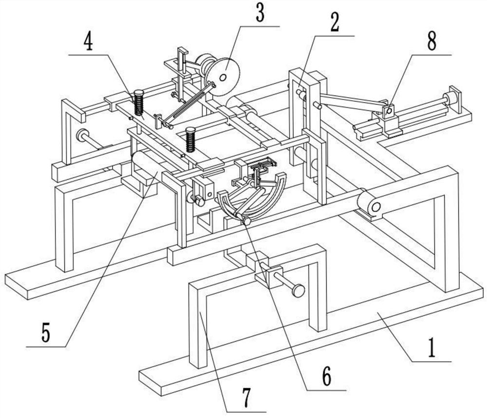
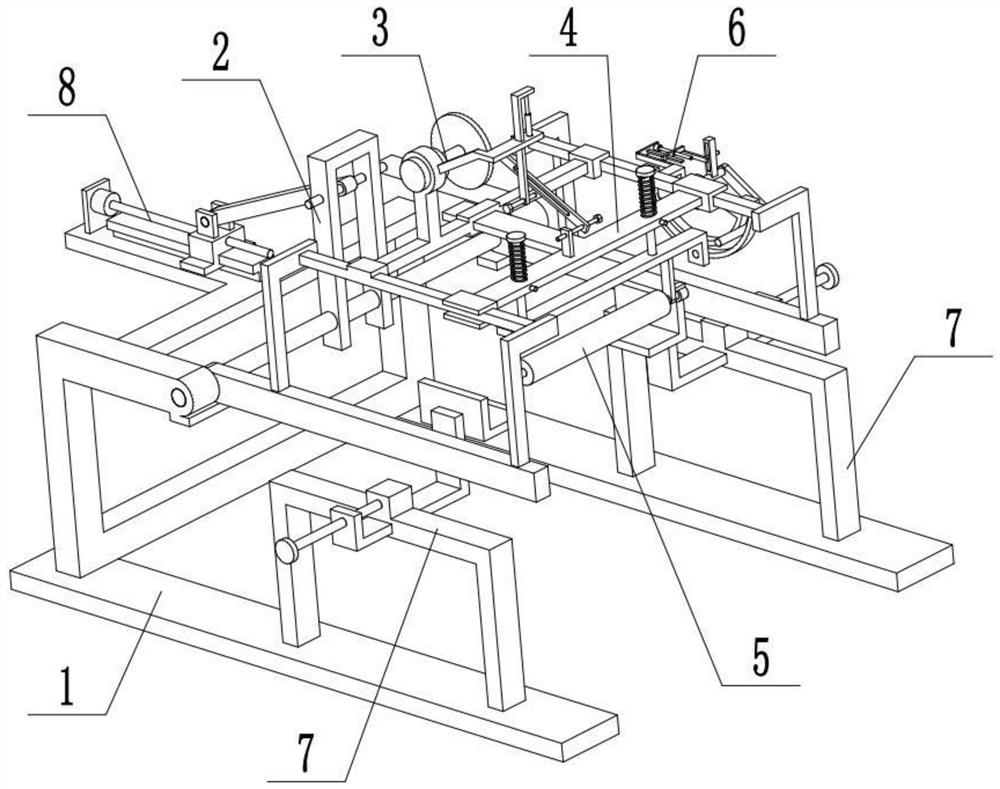
[0033] Combine below Figure 1-7 Describe this embodiment, an LED ceramic substrate processing system, including a base assembly 1, a rotation adjustment seat assembly 2, a reciprocating drive mechanism 3, a reciprocating movement mechanism 4, a grinding mechanism 5, an arc adjustment mechanism 6, a clamping fixture 7 and Angle control mechanism 8, the described rotation adjustment seat assembly 2 is slidingly connected on the base assembly 1, the angle control mechanism 8 is fixedly connected on the base assembly 1, the angle control mechanism 8 is connected with the rotation adjustment seat assembly 2, and the reciprocating drive mechanism 3 Fixedly connected on the rotation adjustment seat assembly 2, the reciprocating movement mechanism 4 is movably connected on the rotation adjustment seat assembly 2, the reciprocating drive mechanism 3 is connected with the reciprocation movement mechanism 4, the grinding mechanism 5 is located at the lower end of the reciprocation moveme...
specific Embodiment approach 2
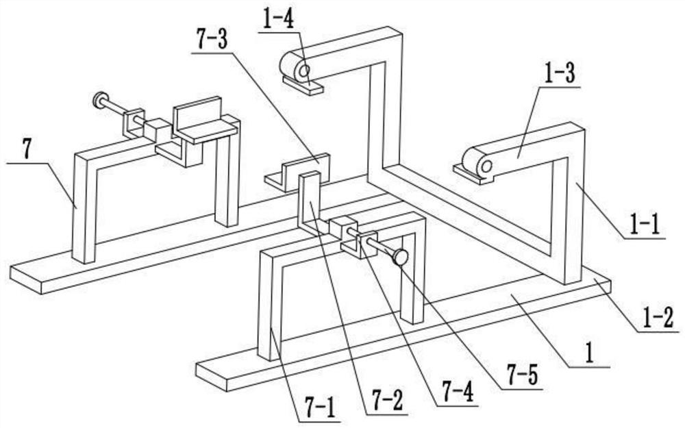
[0035] Combine below Figure 1-7 To illustrate this embodiment, the base assembly 1 includes a U-shaped seat 1-1, a bottom plate 1-2, a hinged seat 1-3 and a limit plate 1-4; the U-shaped seat 1-1 is fixedly connected to the two bottom plates 1 -2, the upper end of the U-shaped seat 1-1 is fixedly connected to two hinged seats 1-3, and the lower ends of the two hinged seats 1-3 are respectively fixedly connected to a limit plate 1-4; the rotation adjustment seat assembly 2 Rotation is connected between the two hinged seats 1-3; the angle control mechanism 8 is arranged on the U-shaped seat 1-1.
specific Embodiment approach 3
[0037] Combine below Figure 1-7 To illustrate this embodiment, the rotation adjustment seat assembly 2 includes a rotating shaft 2-1, a side frame 2-2, a slide bar 2-3, a rod frame 2-4, a portal frame 2-5 and a thin rod 2-6; The two ends of the rotating shaft 2-1 are rotatably connected to the two hinged seats 1-3 respectively, and the two ends of the rotating shaft 2-1 are respectively fixedly connected to a side frame 2-2, and the two slide bars 2-3 pass through the two rod frames 2 respectively. -4 is fixedly connected to the two side frames 2-2, the middle part of the rotating shaft 2-1 is fixedly connected to the portal frame 2-5, the thin rod 2-6 is fixedly connected to the portal frame 2-5, and the thin rod 2-6 It is connected with the angle control mechanism 8; the two side frames 2-2 are attached to the two limit plates 1-4 respectively, and the two limit plates 1-4 play a limiting role on the two side frames 2-2, The two side frames 2-2 are rotated downward to stay...
PUM
 Abstract
Description
Claims
Application Information
 - Generate Ideas
- Intellectual Property
- Life Sciences
- Materials
- Tech Scout
- Unparalleled Data Quality
- Higher Quality Content
- 60% Fewer Hallucinations
Browse by: Latest US Patents, China's latest patents, Technical Efficacy Thesaurus, Application Domain, Technology Topic, Popular Technical Reports.
© 2025 PatSnap. All rights reserved.Legal|Privacy policy|Modern Slavery Act Transparency Statement|Sitemap|About US| Contact US: help@patsnap.com