Method of experimental equipment for discharging polyethylene slurry

An experimental equipment, polyethylene technology, applied in the field of polyethylene, can solve the problems of valve blockage, inability to select the type of the discharge valve, and inability to select or use the instrument equipment, and achieve the effect of continuous discharge.

Pending Publication Date: 2020-10-30
北京拓川科研设备股份有限公司
View PDF0 Cites 0 Cited by
  • Summary
  • Abstract
  • Description
  • Claims
  • Application Information

AI Technical Summary

Problems solved by technology

Usually, the operating conditions of the test device (such as temperature, pressure, process, liquid level, etc.) should match the production device, but due to its particularity (such as the proportional decrease in flow rate), some instrument equipment cannot be selected or use, which requires the development of some new control modes and methods
[0003] The polyethylene reactor slurry discharge equipment of the polyethylene continuous reaction device, the polyethylene reactor slurry contains about 30% (mass fraction) of polyethylene powder, and the particle diameter distribution is 100-500μm, accounting for 85%. If the test device adopts industrial production The discharge method in the device is controlled. In order to prevent the solid particles in the slurry from settling, a certain flow rate needs to be met, which leads to a relatively small diameter of the pipe, which is about 10mm, which makes it impossible to select the discharge valve; if using For conventional regulating valves, when the slurry passes through the narrow gap between the valve seat and the valve core, the large particles and flocs in the slurry may get stuck in the channel, and the solid particles accumulate more and more, thus blocking the entire valve , so that the material in the kettle cannot be discharged, resulting in an accident

Method used


Image

  • Method of experimental equipment for discharging polyethylene slurry
  • Method of experimental equipment for discharging polyethylene slurry

Examples


Embodiment 1

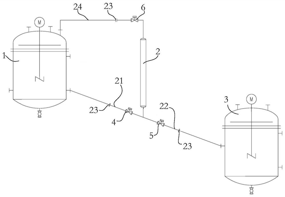
[0039] Such as figure 1 As shown, a kind of experimental equipment for polyethylene slurry discharge of the present embodiment comprises:

[0040] Polymerization reactor 1 for storing polyethylene slurry;

[0041] A discharge tank 2, the discharge tank 2 is connected to the polymerization reactor 1 through a feed pipe 21, and a first valve 4 is installed on the feed pipe 21;

[0042] A flash tank 3, the discharge tank 2 is connected to the flash tank 3 through a discharge pipe 22, and a second valve 5 is installed on the discharge pipe 22;

[0043] Wherein, the end of the feed pipe 21 and the discharge pipe 22 away from the polymerization reactor 1 extends obliquely downward; when the first valve 4 is opened, the polymerization reactor 1 will The polyethylene slurry is transported into the discharge tank 2 under the action of the potential difference; when the second valve 5 is opened, the discharge tank 2 flashes to the discharge tank 2 under the action of the pressure diff...

Embodiment 2

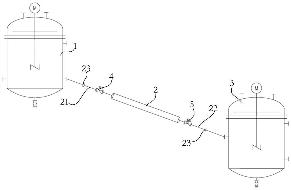
[0055] Such as figure 2 As shown, a kind of experimental equipment for polyethylene slurry discharge of the present embodiment comprises:

[0056] Polymerization reactor 1 for storing polyethylene slurry;

[0057] A discharge tank 2, the discharge tank 2 is connected to the polymerization reactor 1 through a feed pipe 21, and a first valve 4 is installed on the feed pipe 21;

[0058] A flash tank 3, the discharge tank 2 is connected to the flash tank 3 through a discharge pipe 22, and a second valve 5 is installed on the discharge pipe 22;

[0059] Wherein, the end of the feed pipe 21 and the discharge pipe 22 away from the polymerization reactor 1 extends obliquely downward; when the first valve 4 is opened, the polymerization reactor 1 will The polyethylene slurry is transported into the discharge tank 2 under the action of the potential difference; when the second valve 5 is opened, the discharge tank 2 flashes to the discharge tank 2 under the action of the pressure dif...


PUM


Abstract

The invention relates to experimental equipment for discharging polyethylene slurry. The experimental equipment comprises a polymerization reaction kettle for storing the polyethylene slurry; a discharging tank which is connected with the polymerization reaction kettle through a feeding pipe, wherein a first valve is mounted on the feeding pipe; a flash tank, wherein the discharging tank is connected with the flash tank through a discharging pipe, and a second valve is installed on the discharging pipe; one end, far away from the polymerization reaction kettle, of each of the feeding pipe andthe discharging pipe extends downwards in an inclined manner; when the first valve is opened, polyethylene slurry is conveyed into the discharging tank by the polymerization reaction kettle under theaction of pressure difference or / and liquid level difference; and when the second valve is opened, the discharge tank conveys the polyethylene slurry into the flash tank under the action of pressure difference or / and liquid level difference. The discharging tank is arranged between the first valve and the second valve, liquid filling and discharging circulation operation is conducted on the discharging tank by switching on and off of the first valve and the second valve, and continuous discharging of slurry in the reaction kettle can be achieved.

Description

technical field [0001] The invention relates to the technical field of polyethylene, in particular to a polyethylene reactor slurry discharge experimental equipment and method of a polyethylene continuous reaction test device. Background technique [0002] The test device is mainly responsible for the development of high-end product technology, while carrying out the development of a series of cutting-edge fields such as catalyst research and development, and improving the research and development progress. Usually, the operating conditions of the test device (such as temperature, pressure, process, liquid level, etc.) should match the production device, but due to its particularity (such as the proportional decrease in flow rate), some instrument equipment cannot be selected or Therefore, some new control modes and methods need to be developed. [0003] The polyethylene reactor slurry discharge equipment of the polyethylene continuous reaction device, the polyethylene reac...

Claims


Application Information

Patent Timeline
IPC IPC(8): B01J4/00B01J19/18C08F10/02C08F2/01
CPCB01J4/001B01J4/008B01J19/1862C08F10/02C08F2/01
Inventor 刘柏青张仁亮
Owner 北京拓川科研设备股份有限公司
Why Eureka
Try Eureka