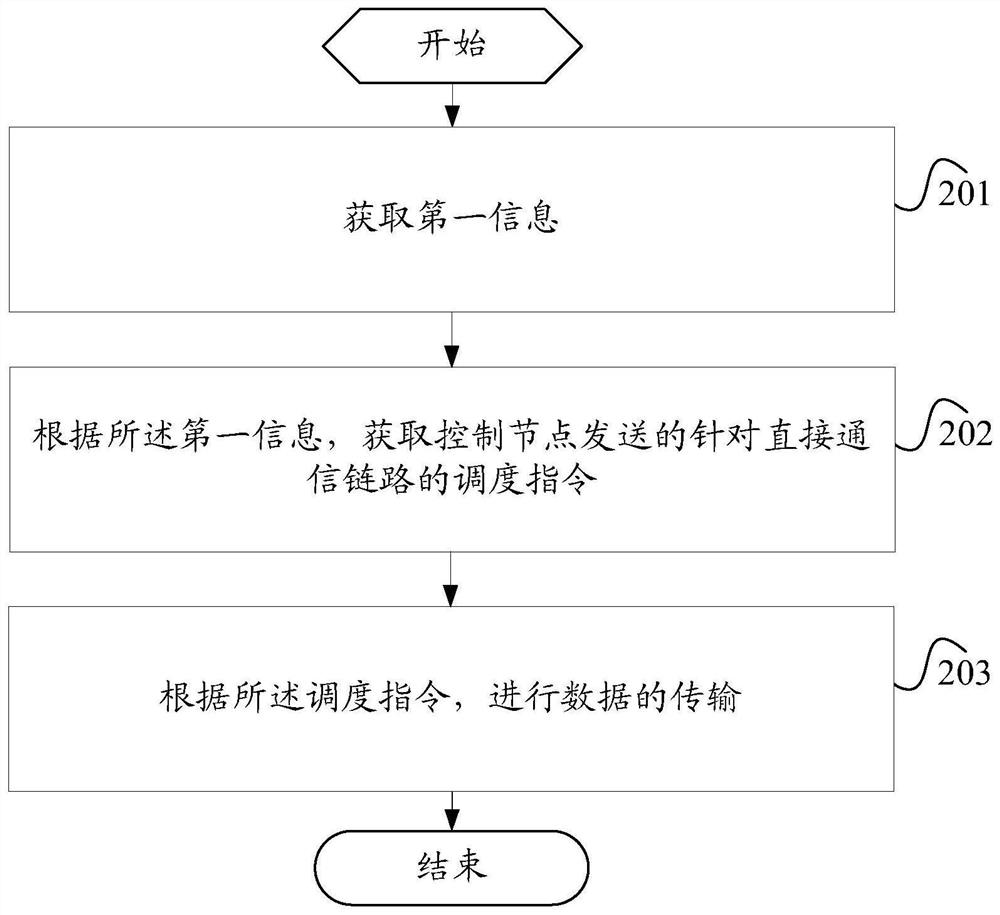
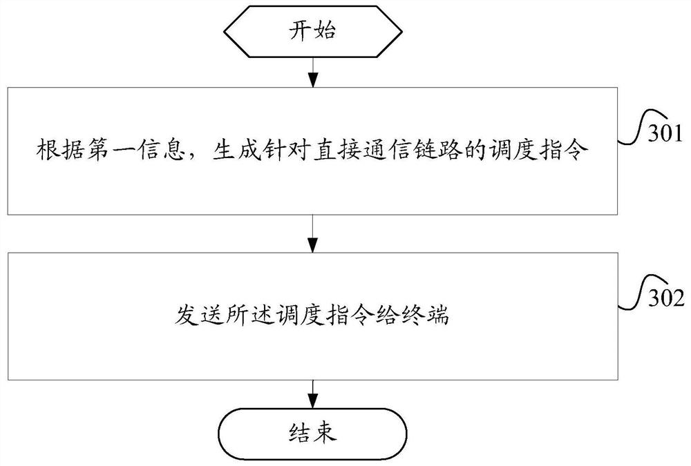
Data transmission method, data sending method, terminal and control node
A technology of a data transmission method and a data sending method, which is applied in the field of communication, can solve problems such as increasing scheduling delay sidelink overhead, and achieve the effect of reducing scheduling delay and direct communication link resource overhead
- Summary
- Abstract
- Description
- Claims
- Application Information
AI Technical Summary
Problems solved by technology
Method used
Image

Examples
example 1
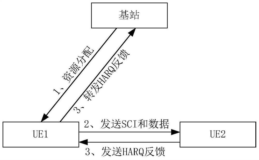
[0162] Example 1. The base station configures the same DCI for the terminal, and the transmission status indicated by the transmission indication field is data transmission
[0163] 1. When performing direct communication link unicast
[0164] A31. The base station allocates RNTIs (for example, SL-G-RNTI) to UE1 and UE2 for sidelink transmission, and allocates transmission IDs of UE1 and UE2 to 0 and 1, respectively.
[0165] A32. The base station schedules UE1 to send sidelink unicast data to UE2. The base station generates and schedules DCI (for example, DCI format 3-1) to UE1 and UE2, where the transmission indication field is 0, and scrambles the DCI using SL-G-RNTI, and passes PDCCH transmission.
[0166] A33, UE1 and UE2 use SL-G-RNTI to monitor the PDCCH, decode and demodulate the scheduling DCI.
[0167] A34. UE1 finds that the transmission identification ID assigned to it in the transmission indication field is 0, and thus knows that it is the sending UE; UE2 finds ...
example 2
[0178] Example 2. The base station configures the same DCI for the terminal, and the transmission status indicated by the transmission indication field is data reception and direct communication link unicast
[0179] A51. The base station allocates RNTIs (for example, SL-G-RNTI) to UE1 and UE2 for sidelink transmission, and allocates transmission identifiers IDs 0 and 1 to UE1 and UE2 respectively.
[0180] A52. The base station schedules UE1 to send sidelink unicast data to UE2, and the base station generates and schedules DCI (for example, DCI format 3-1) to UE1 and UE2, where the transmission ID in the transmission indication field is 1, and scrambled using SL-G-RNTI The DCI is sent through the PDCCH.
[0181] A53, UE1 and UE2 use SL-G-RNTI to monitor the PDCCH, decode and demodulate the scheduling DCI.
[0182] A54. UE2 finds that the transmission indication field assigned to it is 1, and thus knows that it is the receiving UE; UE1 finds that the transmission indication f...
example 3
[0185] Example 3. The base station configures the same DCI for the terminal, and the transmission status indicated by the transmission indication field is data reception and data transmission, and direct communication link unicast
[0186] A61. The base station allocates RNTIs (for example, SL-G-RNTI) to UE1 and UE2 for sidelink transmission, and allocates transmission identifiers IDs 0 and 1 to UE1 and UE2 respectively.
[0187] A62. The base station schedules UE1 to send sidelink unicast data to UE2, and the base station generates scheduling DCI (for example, DCI format 3-1) to UE1 and UE2, where the transmission ID in the transmission indication field includes 0 and 1, 0 indicates the sending end, and 1 Indicates that the receiving end uses SL-G-RNTI to scramble the DCI and sends it through the PDCCH.
[0188] A63, UE1 and UE2 use the SL-G-RNTI to monitor the PDCCH, decode and demodulate the scheduling DCI.
[0189] A64. UE1 discovers that the transmission ID assigned to i...
PUM
 Abstract
Description
Claims
Application Information
 - Generate Ideas
- Intellectual Property
- Life Sciences
- Materials
- Tech Scout
- Unparalleled Data Quality
- Higher Quality Content
- 60% Fewer Hallucinations
Browse by: Latest US Patents, China's latest patents, Technical Efficacy Thesaurus, Application Domain, Technology Topic, Popular Technical Reports.
© 2025 PatSnap. All rights reserved.Legal|Privacy policy|Modern Slavery Act Transparency Statement|Sitemap|About US| Contact US: help@patsnap.com