
Single-layer microstrip dual-polarization transmission array antenna and manufacturing method

A manufacturing method and a dual-polarization technology, which are applied to antenna unit combinations, antennas, and antenna components with different polarization directions, can solve the problems of rising manufacturing costs and increasing the complexity of dual-polarization planar transmission array antennas, etc.

Inactive Publication Date: 2020-10-27
GUANGXI UNIVERSITY OF TECHNOLOGY
View PDF7 Cites 3 Cited by
  • Summary
  • Abstract
  • Description
  • Claims
  • Application Information

AI Technical Summary

Problems solved by technology

[0003] However, since the transmission phase shift provided by the frequency selective surface unit is much smaller than 360 degrees under the limitation of the transmission amplitude of 3dB, the traditional dual-polarization transmission array antenna usually needs to use a multi-layer frequency with more than three layers of dielectric plates. Selecting the structure as the array unit greatly increases the complexity of manufacturing the dual-polarization planar transmission array antenna, which leads to an increase in manufacturing costs
So far, there has been no related technology to realize dual-polarized transmissive array antennas on a single-layer microstrip

Method used


Image

  • Single-layer microstrip dual-polarization transmission array antenna and manufacturing method
  • Single-layer microstrip dual-polarization transmission array antenna and manufacturing method
  • Single-layer microstrip dual-polarization transmission array antenna and manufacturing method

Examples


Embodiment 1

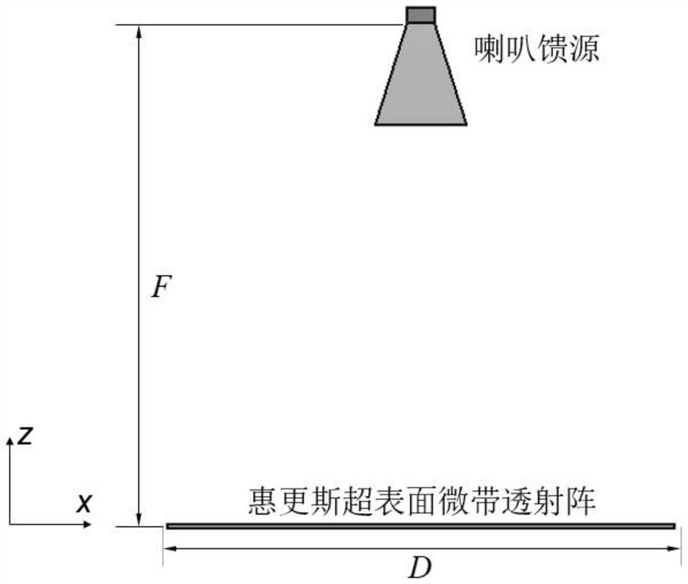
[0051] Such as figure 1As shown, a single-layer microstrip dual-polarized transmission array antenna based on Huygens metasurface, the antenna is composed of a horn feed and a Huygens metasurface microstrip dual-polarization transmission array; the horn feed consists of a waveguide and a horn The opening is formed; the Huygens metasurface microstrip dual-polarization transmission array is composed of N*N symmetrical metasurface transmission units.

[0052] Preferably, the waveguide is a standard waveguide BJ260, and the diameter of the waveguide is a*b=8.636*4.318mm 2 , the opening diameter of the horn is A*B=31*22mm 2 , The overall height of the horn is L=42mm.

[0053] Preferably, the aperture of the Huygens metasurface microstrip dual-polarization transmission array is D*D, in order to effectively form a radiation beam with high gain and low sidelobe, the aperture D of the Huygens metasurface microstrip dual-polarization transmission array *D should be greater than 10λ ...

Embodiment 2

[0061] A method for manufacturing a single-layer microstrip dual-polarized transmission array antenna based on a Huygens metasurface, comprising the following steps:

[0062] Step 1: According to the phase distribution optimization, obtain the aperture phase distribution of the single-layer microstrip dual-polarization transmission array antenna of the Huygens metasurface: firstly, select and determine the single-layer microstrip dual-polarization transmission array antenna of the Huygens metasurface The initial parameters include the horn feed position F (the distance between the horn opening and the Huygens metasurface microstrip dual-polarization transmission array), the central operating frequency f of the Huygens metasurface microstrip dual-polarization transmission array 0 , the aperture size D of the Huygens metasurface microstrip dual-polarization transmission array, and the number of metasurface transmission units In order to form a symmetrical uniform beam, N is gen...

Embodiment 3

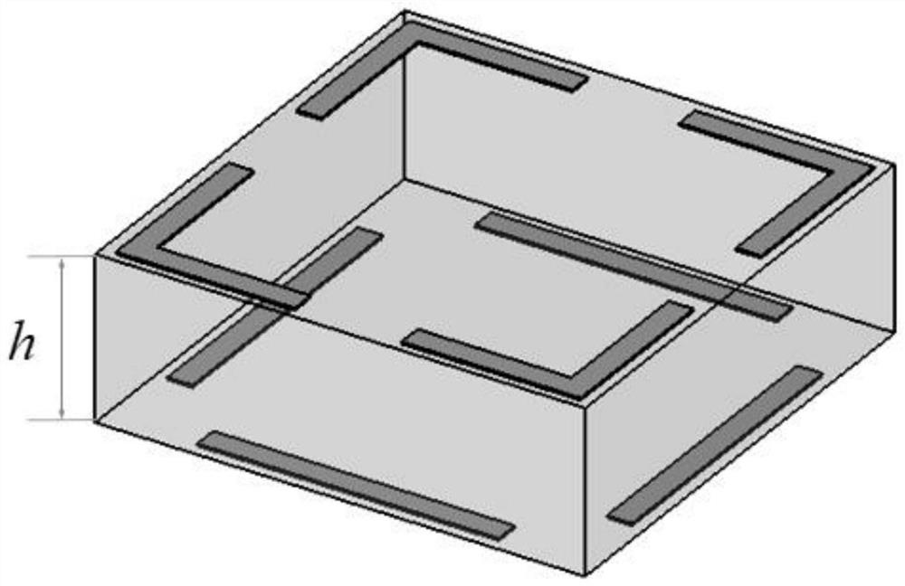
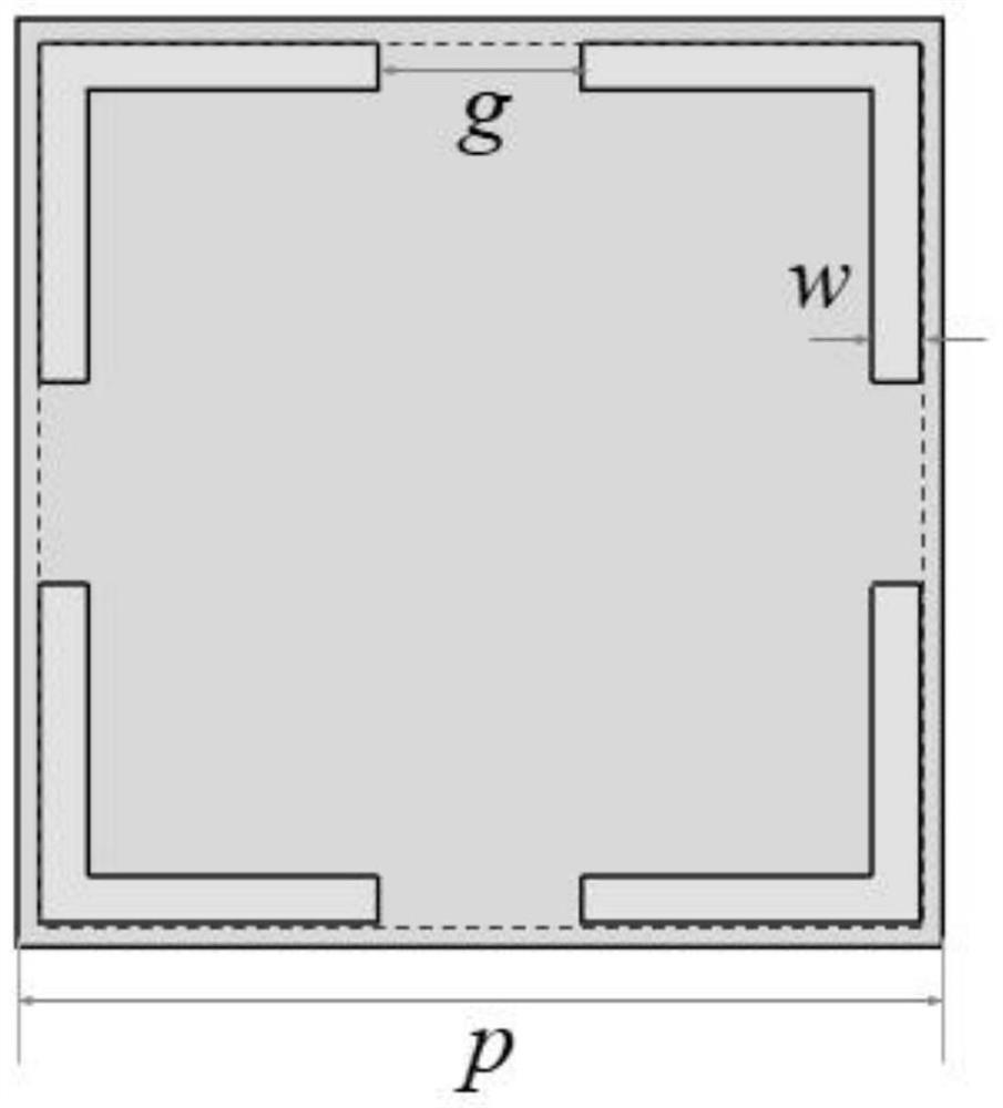
[0076] The advantage of the Huygens supersurface microstrip dual-polarization transmission array antenna designed by the present invention is that the dual-polarization function has low side lobe and high gain, and the single-layer dielectric plate design has no through hole, light weight, low cost and Easy to assemble and integrate. The structural parameters of the central transmission unit of the metasurface microstrip dual-polarization transmission array are p = 5mm, w = 0.2mm, s = 4.8mm, g = 1mm, l = 3.4mm, the topological structure of other units see Figure 7-8 ; Central operating frequency f of the dual-polarized transmission array antenna of the present invention 0 =28GHz, N=33, D=165mm, F=159mm.

[0077] For verifying the correctness of the design method of the present invention, as Figure 9-10 As shown, given the Huygens metasurface microstrip dual-polarized transmission array at the center frequency f 0 = The simulated normalized radiation pattern at 28GHz, it c...


PUM

PropertyMeasurementUnit
Caliber sizeaaaaaaaaaa
Heightaaaaaaaaaa

Abstract

The invention discloses a single-layer microstrip dual-polarization transmission array antenna and a manufacturing method. The antenna is composed of a horn feed source and a Huygens metasurface microstrip dual-polarization transmission array. The horn feed source is composed of a waveguide and a horn opening, and the Huygens metasurface microstrip dual-polarization transmission array is composedof N * N metasurface transmission units. The metasurface transmission unit is composed of two layers of composite metal structures with biaxial symmetry on an xy plane and a single-layer dielectric plate, and the composite metal structure on the upper layer is formed by opening gaps on four sides of a square metal frame, and the composite metal structure on the lower layer is formed by removing four corners on a square metal frame. The dual-polarization transmission array antenna is manufactured based on a single-layer dielectric plate, through holes do not need to be punched, and the performance of the dual-polarization transmission array antenna meets the beneficial effects of low sidelobe, high gain, high aperture efficiency, enough bandwidth and the like, so that the dual-polarizationtransmission array antenna is easier to manufacture, lower in cost and easier to assemble and integrate under the condition that the same performance of a traditional transmission array antenna is achieved.

Description

technical field [0001] The invention belongs to the field of single-layer microstrip dual-polarization transmission array antennas, in particular to a single-layer microstrip dual-polarization transmission array antenna based on Huygens metasurface and a manufacturing method. Background technique [0002] The planar transmission array antenna is a new type of array antenna that combines the advantages of the traditional parabolic antenna and the microstrip array antenna. Among them, the dual-polarized planar transmission array antenna can integrate two antennas with mutually orthogonal polarization directions, and work in the duplex mode of transmitting and receiving at the same time, so its most prominent advantage is to save the number of antennas for a single directional base station. Due to its planar configuration, it has the advantages of small size, light weight, low manufacturing cost, and easy integration. Dual-polarized planar transmission array antennas have been ...

Claims


Application Information

Patent Timeline
IPC IPC(8): H01Q15/00H01Q1/24H01Q21/24G06F30/18G06F30/20
CPCG06F30/18G06F30/20H01Q1/241H01Q15/0086H01Q21/24
Inventor 薛春华黄有桢牛乐黄力何柏灵
Owner GUANGXI UNIVERSITY OF TECHNOLOGY
Learn More