Eureka AIR delivers breakthrough ideas for toughest innovation challenges, trusted by R&D personnel around the world.

Device for cooling battery

A vehicle and battery technology, applied in the direction of secondary batteries, vehicle components, battery temperature control, etc., can solve the problems of expensive, a lot of installation work, a lot of assembly costs, etc.

Pending Publication Date: 2020-10-27
MAHLE INT GMBH
View PDF5 Cites 0 Cited by
  • Summary
  • Abstract
  • Description
  • Claims
  • Application Information

AI Technical Summary

Problems solved by technology

[0007] The disadvantage of the first description of the device for cooling a vehicle battery in a motor vehicle is that many lines and T-pieces are required for the realization of the device, which in turn requires a lot of installation work and is therefore very expensive
However, the disadvantage is that it requires a lot of assembly costs and a lot of parts due to the extra piping, T-pieces, switching valves, and thus an additional large amount of assembly work

Method used


Image

  • Device for cooling battery
  • Device for cooling battery
  • Device for cooling battery

Examples


Embodiment Construction

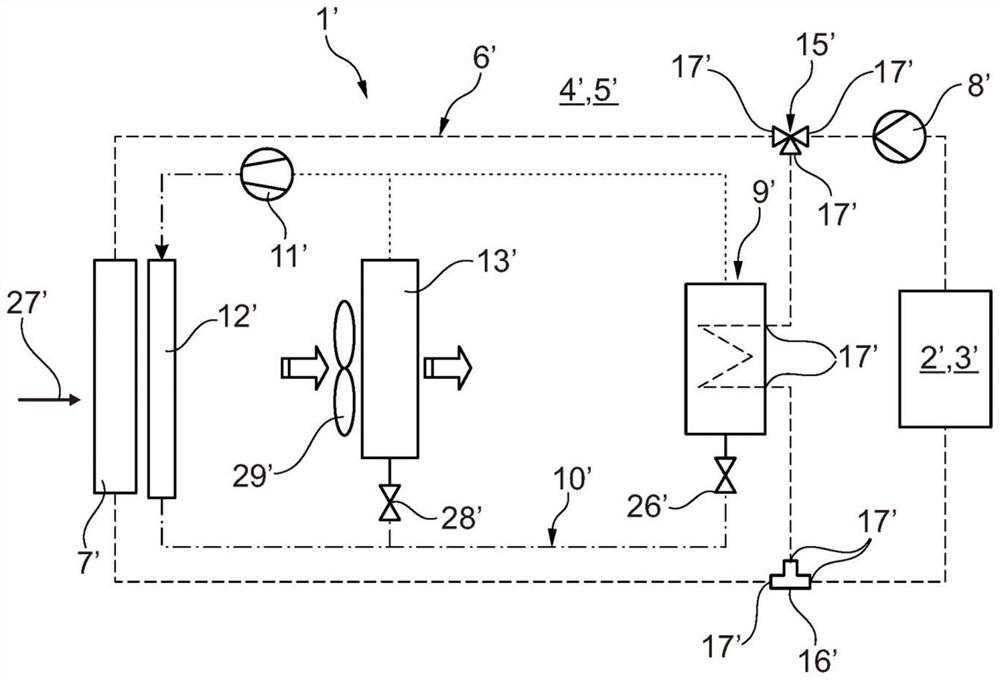
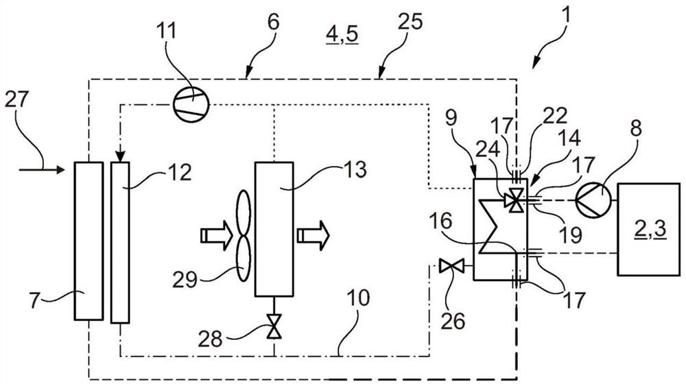
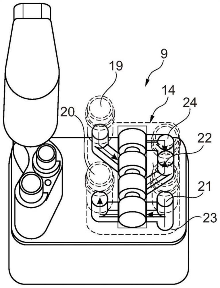
[0030] refer to figure 2 , the device 1 according to the invention for temperature control / cooling of a heat source 2 , eg a vehicle battery 3 , in a motor vehicle 4 , such as an electric or hybrid vehicle 5 , comprises a coolant circuit 6 in which A heat source 2 or vehicle battery 3, a coolant cooler 7, a coolant pump 8 and a refrigerator 9 are arranged (see also Figures 3 to 6 ). In addition, a refrigerant circuit 10 is provided, in which a refrigerator 9 , a compressor 11 , a condenser 12 and an evaporator 13 are arranged. in the same way, on the same basis figure 1 The prior art device 1' shown has an arrangement in which the figure 1 In , reference numerals are used in a similar manner, but with apostrophes.

[0031] According to the invention, the first valve device 14 is now arranged in the refrigerator 9 or directly on the refrigerator, wherein, via the first valve device 14 , the coolant flow 25 can flow between the refrigerator 9 and the coolant cooler 7 dist...


PUM


Abstract

The invention relates to a device (1) for controlling the temperature of a vehicle battery (3) in an electric or hybrid vehicle (5), comprising: a coolant circuit (6) in which the vehicle battery (3),a coolant cooler (7), a coolant pump (8) and a refrigerator (9) are arranged; and a refrigerant circuit (10) in which the refrigerator (9), the compressor (11), the condenser (12) and the evaporator(13) are arranged. It is essential to the invention that a first valve device (14) is arranged in or directly on the refrigerator (9), by means of which first valve device a coolant flow (25) can be distributed between the refrigerator (9) and the coolant cooler (7). In this way, the types of parts and the assembly workload can be reduced.

Description

technical field [0001] The invention relates to a device with a coolant circuit for temperature control of a vehicle battery in a motor vehicle and to a coolant circuit according to the preamble of claim 1 . The invention also relates to an electric or hybrid vehicle with such a device. Background technique [0002] A general device for cooling a vehicle battery in a motor vehicle is known from DE 10 2008 017 113 A1, which has a coolant circuit in which the vehicle battery, a coolant cooler, a coolant pump and refrigerator. The refrigerator is also connected into a refrigerant circuit, in which a compressor, a condenser and an evaporator are also arranged. However, connecting the coolant circuit into the refrigerant circuit via the cooler is relatively complicated. [0003] From DE 10 2009 054 186 A1 a system is known for heating or cooling the battery of a motor vehicle and the interior of the motor vehicle, the system comprising: a coolant circuit thermally coupled to t...

Claims


Application Information

Patent Timeline
IPC IPC(8): H01M10/613H01M10/625H01M10/6567H01M10/66B60H1/00B60H1/32
CPCH01M10/613H01M10/625H01M10/6567H01M10/66B60H1/00271B60H1/3204Y02E60/10H01M10/663H01M10/6568H01M10/6569
Inventor 马库斯·韦斯纳
Owner MAHLE INT GMBH
Why Eureka
Eureka Blog
Learn More