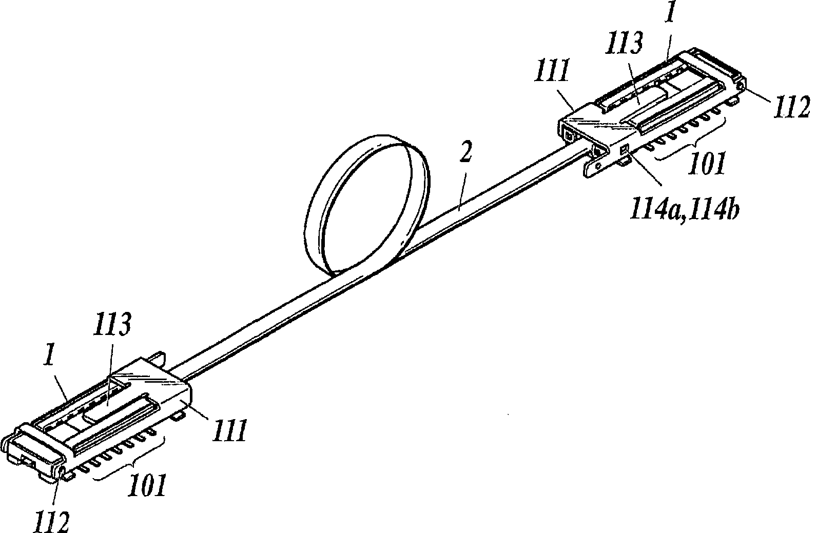
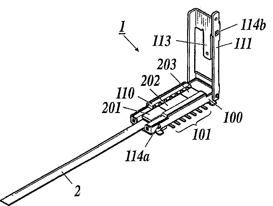
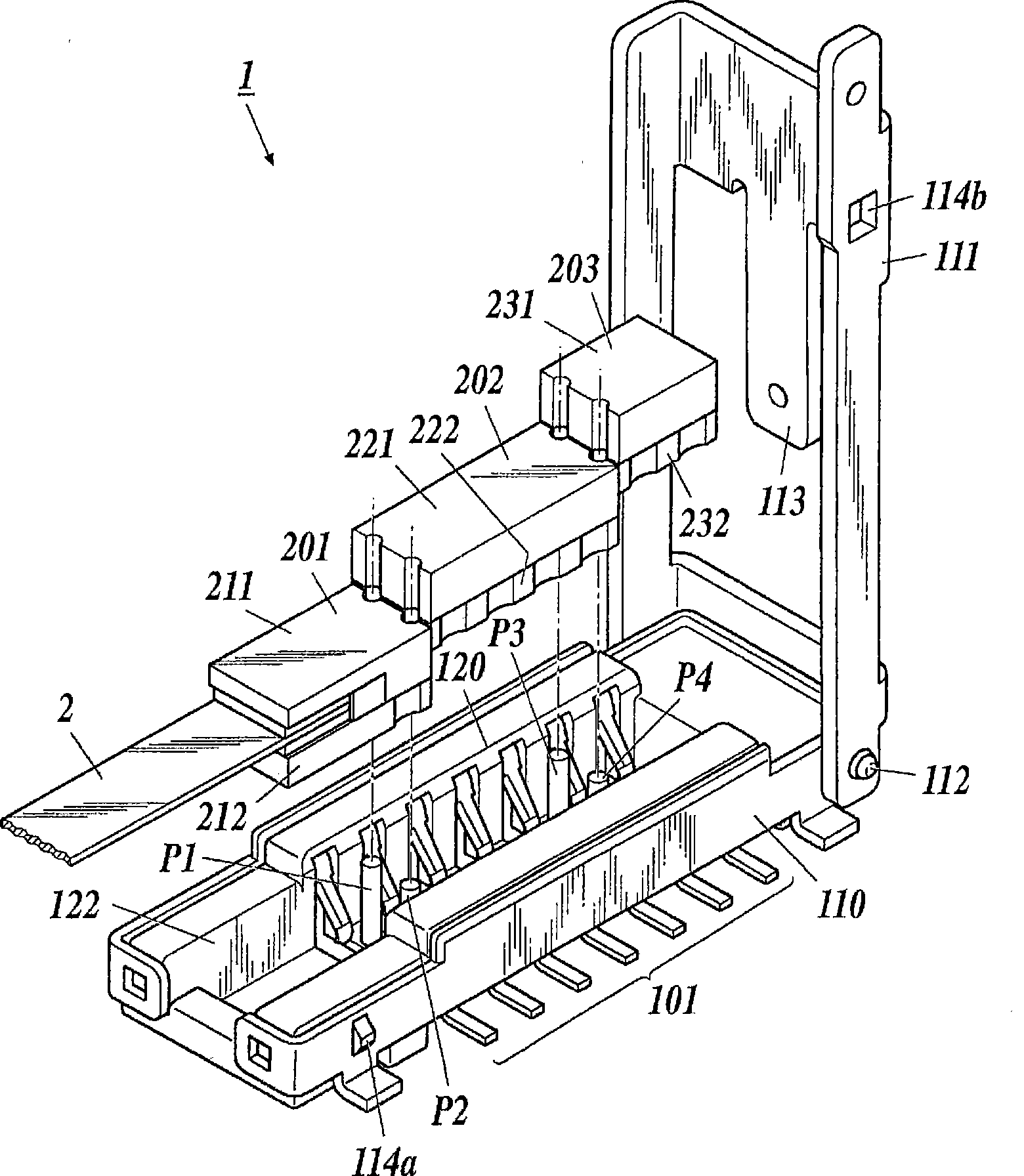
Electrooptic conversion module
A technology of electro-optic conversion and photoelectric conversion elements, applied in optics, light guides, circuits, etc., can solve uneconomical problems and achieve the effect of economical replacement
- Summary
- Abstract
- Description
- Claims
- Application Information
AI Technical Summary
Problems solved by technology
Method used
Image
Examples
Deformed example 1
[0052] Second, refer to Figure 8A , Figure 8B , Figure 8C An electro-optical conversion module 1a as a modified example of the above-mentioned electro-optical conversion module 1 will be described. Figure 8A Shown is an example of embedding of the division unit of the electro-optic conversion module 1a of Modification 1, Figure 8B Shown is an example of the conductive protrusion H provided in the fitting portion 120a, Figure 8C Shown is an example of the bottom surface of the connecting portion of the optical signal transmitting / receiving unit 201a and the amplifier unit 202a. In addition, the same components as those of the above-mentioned electro-optical conversion module 1 are denoted by the same reference numerals and their descriptions are omitted.
[0053] like Figure 8A As shown, the electro-optical conversion module 1a has a fitting portion 120a on the connector body 110a that engages the optical signal transmitting and receiving portion 201a, the amplifyin...
Deformed example 2
[0059] Next, refer to Figure 9 An electro-optic conversion module 1 b as a modified example of the above-mentioned electro-optic conversion module 1 will be described. Figure 9 Shown is an example of embedding of division units in the electro-optical conversion module 1 b of Modification 2. FIG. In addition, the same reference numerals are assigned to the same configurations as those of the electro-optical conversion module 1 described above, and description thereof will be omitted.
[0060] like Figure 9 As shown, the electro-optical conversion module 1b has a fitting part 120b on the connector main body 110b that engages the optical signal transmitting and receiving part 201b, the amplifying part 202b and the communication control part 203b in an embedded manner. The fitting portion 120b may lock each divided unit using the above-mentioned pins or conductive protrusions, or may be locked only by contact with the socket contact portion 121, and is not particularly limite...
Deformed example 3
[0064] Next, refer to Figure 10A , Figure 10B , Figure 10C An electro-optical conversion module 1c as a modified example of the above-mentioned electro-optical conversion module 1 will be described. Figure 10A Shown is an example of embedding of the division unit of the electro-optical conversion module 1c of Modification 3, Figure 10B Shown is the above example of the optical signal transmission and reception unit 201c, the amplification unit 202c and the communication control unit 293c, Figure 10C Shown is an example of the connecting portion of the optical signal transmission / reception unit 201c and the amplifier unit 202c. In addition, the same reference numerals are assigned to the same configurations as those of the electro-optical conversion module 1 described above, and description thereof will be omitted.
[0065] like Figure 10AAs shown, the electro-optical conversion module 1c has a fitting part 120c embedded in and locking the optical signal transmittin...
PUM
 Abstract
Description
Claims
Application Information
 - Generate Ideas
- Intellectual Property
- Life Sciences
- Materials
- Tech Scout
- Unparalleled Data Quality
- Higher Quality Content
- 60% Fewer Hallucinations
Browse by: Latest US Patents, China's latest patents, Technical Efficacy Thesaurus, Application Domain, Technology Topic, Popular Technical Reports.
© 2025 PatSnap. All rights reserved.Legal|Privacy policy|Modern Slavery Act Transparency Statement|Sitemap|About US| Contact US: help@patsnap.com


