
Position and angle adjustable ball cage retainer grinding tool

A technology for cages and ball cages, applied in grinding machines, manufacturing tools, grinding drives, etc., can solve problems such as missed grinding, limited diameter and length, and inability to grind and polish rectangular windows

Active Publication Date: 2020-10-27
王河水
View PDF9 Cites 5 Cited by
  • Summary
  • Abstract
  • Description
  • Claims
  • Application Information

AI Technical Summary

Problems solved by technology

[0006] The object of the present invention is to provide a kind of abrasive tool of the ball cage cage that position and angle can be adjusted, to solve the above-mentioned background technology because most of the rotating grinding parts (i.e. buffing wheels) are circular structures, their diameter length is limited , it is not suitable for grinding and polishing the longer sides of the rectangular window, resulting in insufficient polishing and comprehensive, prone to the problem of missing grinding

Method used


Image

  • Position and angle adjustable ball cage retainer grinding tool
  • Position and angle adjustable ball cage retainer grinding tool
  • Position and angle adjustable ball cage retainer grinding tool

Examples


Embodiment Construction

[0029] The following will clearly and completely describe the technical solutions in the embodiments of the present invention with reference to the accompanying drawings in the embodiments of the present invention. Obviously, the described embodiments are only some, not all, embodiments of the present invention.

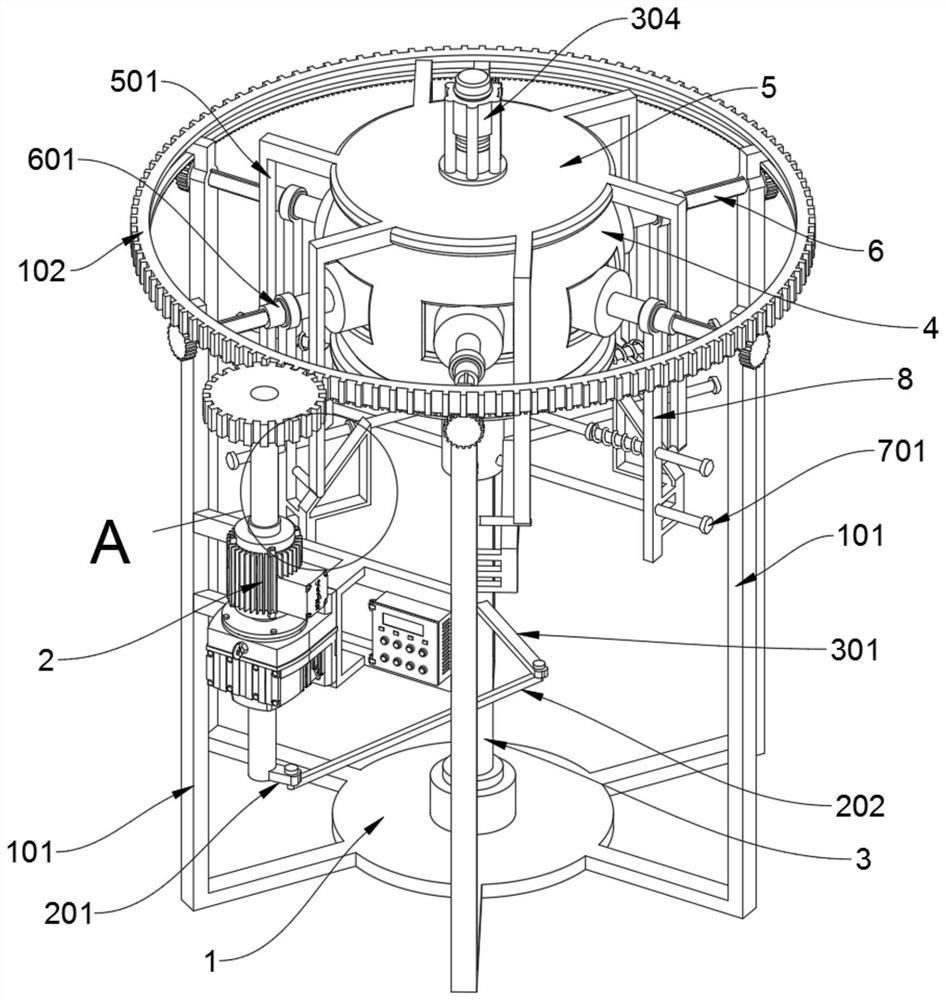
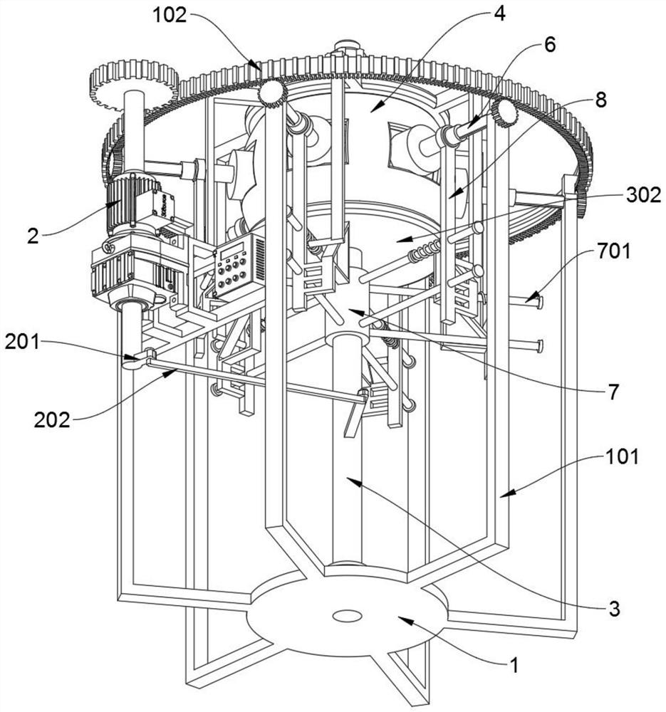
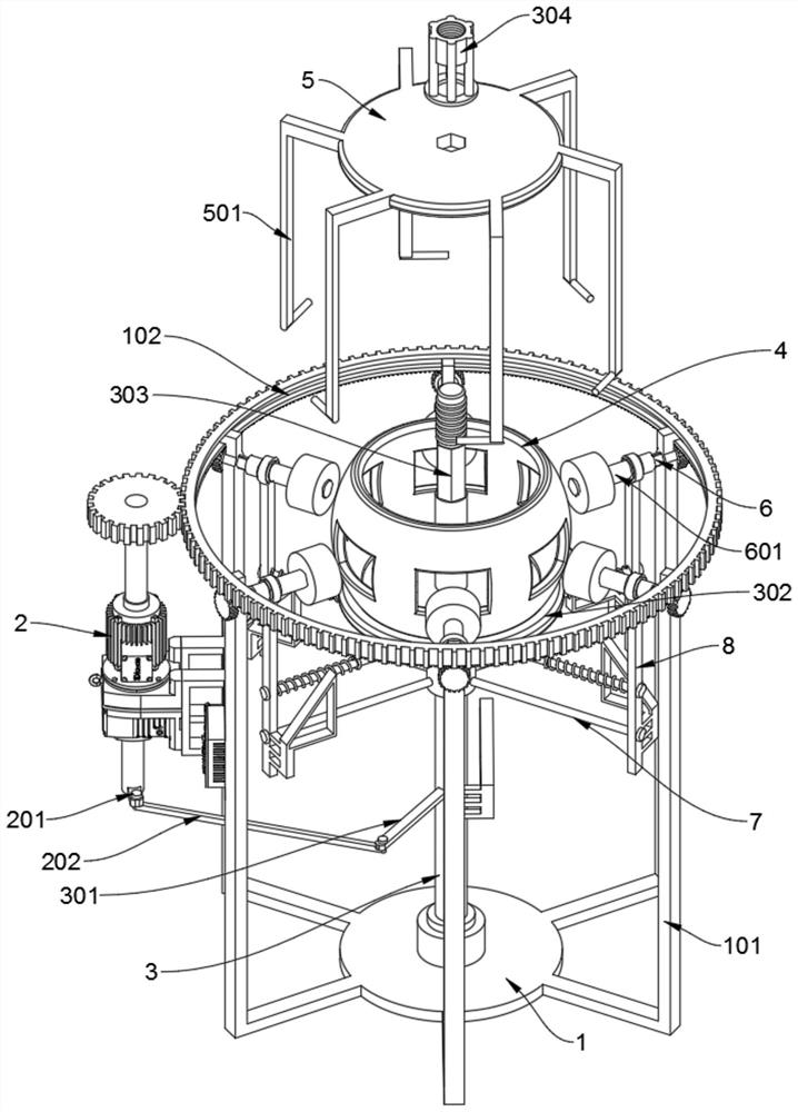
[0030] see Figure 1 to Figure 8 , an embodiment provided by the present invention: a grinding tool for a ball cage with adjustable position and angle, including a base 1, the base 1 includes a vertical support leg 101 and a gear ring 102, the base 1. The whole is formed by the joint welding combination of the central circular chassis and the six vertical legs 101 supported in a circular array. The tops of the six vertical legs 101 are all welded and supported with an L positioning claw, and the ring gear 102 is rotated Installed on the six L positioning claws; a motor 2 is vertically locked on the middle section of the vertical support leg 101 in the two places on t...


PUM


Abstract

The invention discloses a position and angle adjustable ball cage retainer grinding tool, and relates to the technical field of automobile accessory grinding equipment. The problems that in existing grinding equipment, a rotary grinding part (namely a grinding plate) is mostly in a circular structure, and is limited in diameter and length, so that the grinding part cannot be suitable for polishingtwo long sides of a rectangular window, and polishing is caused not thorough and comprehensive, and polishing omission is prone to occur. The position and angle adjustable ball cage retainer grindingtool comprises a base, wherein the base is integrally formed by welding and combining a central circular bottom plate and six vertical supporting legs for supporting in an annular array manner, wherein the top ends of the six vertical supporting legs are provided with L positioning clamping jaws in a welded and supported mode, and a toothed ring is mounted on the six L positioning clamping jaws in a sleeve rotating manner. Six position springs on six positioning shaft rods in the tool can perform rebounding, pushing, pulling and resetting on six vertical support positioning frames, six shaftsleeves and wire drawing polishing wheels, so that the trouble of manual sequential pulling of the six wire drawing polishing wheels is omitted.

Description

technical field [0001] The invention relates to the technical field of grinding equipment for auto parts, in particular to a grinding tool for a cage cage with adjustable positions and angles. Background technique [0002] The ball cage is also called "constant velocity universal joint" and is an important part of the transmission system of a car. Its function is to transmit the power of the engine from the transmission to the two front wheels to drive the car to run at high speed. Among them, the ball cage cage is one of the very important parts of the ball cage. [0003] Due to the special structure of the cage, when the window surface of the cage is polished, an abrasive tool for the cage cage is required. [0004] For example, the patent No. CN201721213393.X discloses an abrasive tool for a ball cage cage with adjustable position and angle, which belongs to the field of processing machinery for ball cage universal joints, including machine tools, sliding saddles, slidin...

Claims


Application Information

Patent Timeline
IPC IPC(8): B24B29/02B24B27/00B24B41/06B24B47/12B24B47/20B24B47/22B24B41/00
CPCB24B27/0023B24B27/0076B24B29/02B24B41/00B24B41/06B24B47/12B24B47/20B24B47/22
Inventor 王河水
Owner 王河水
Learn More