


Quick Research
Generate reliable direction feasibility study reports for your R&D in just a few steps.

Technical Q&A
Discover and master advanced knowledge NOW. Basics, ideas, possibilities, all at once.

Find Solutions
As an expert in R&D theories, this can generate solutions to your technical problems instantly.

Evaluate Feasibility
Analyze your overall solution with one click, know your potential R&D risks in advance.

Monitor Landscape
Get weekly tech updates, stay abreast of the latest tech innovations and key insights.
Fundus imaging system
An imaging system and imaging objective lens technology, applied in the field of optics, can solve problems such as uneven illumination, poor use effect, and small focus range
- Summary
- Abstract
- Description
- Claims
- Application Information
AI Technical Summary
Problems solved by technology
Method used
Image

Examples
Embodiment 1
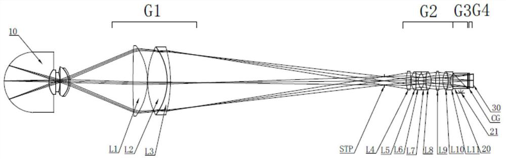
[0034] Embodiment one: if figure 1 As shown, a fundus imaging system, from the object plane side to the image plane side includes:
[0035] The eyepiece group G1 with positive dioptric power, the imaging objective lens group G2 with positive dioptric power, the gaze assembly G3, the auxiliary assembly G4 and the sensor 30; when the eye is checked, the eyeball 10 is located on the left side of the eyepiece group G1.
[0036] The staring assembly G3 includes a dichroic prism 20 and a fixation lamp 21, and the dichroic prism 20 is arranged between the auxiliary assembly G4 and the imaging objective lens group G2, that is, the dichroic prism 20 can be arranged on the main optical axis of the fundus imaging system; The direction perpendicular to the optical axis of the fundus imaging system is arranged on the outside of the dichroic prism 20 . Specifically, in this embodiment, the fixation lamp 21 can be arranged on the lower side of the dichroic prism 20 .
[0037] When the eyeba...
Embodiment 2
[0058] Embodiment 2: a fundus imaging system. The difference between this embodiment and Embodiment 1 lies in the specific structure of the eyepiece group G1.
[0059] On the basis of Embodiment 1, in this embodiment, the eyepiece group G1 sequentially includes from the object plane side to the image plane side:
[0060] The first lens L1 with positive refractive power, the second lens L2 with positive refractive power and the third lens L3 with negative refractive power, the second lens L2 and the third lens L3 are cemented.
[0061] In this embodiment, the setting of the positive and negative structure reduces the effective aperture of the rear imaging objective lens group G2, the staring component G3 and the auxiliary component G4, and realizes the miniaturization of the fundus imaging system; meanwhile, the setting of the cemented lens greatly The chromatic aberration and astigmatism of imaging are improved, and the quality of imaging is increased.
[0062] Preferably, th...
Embodiment 3
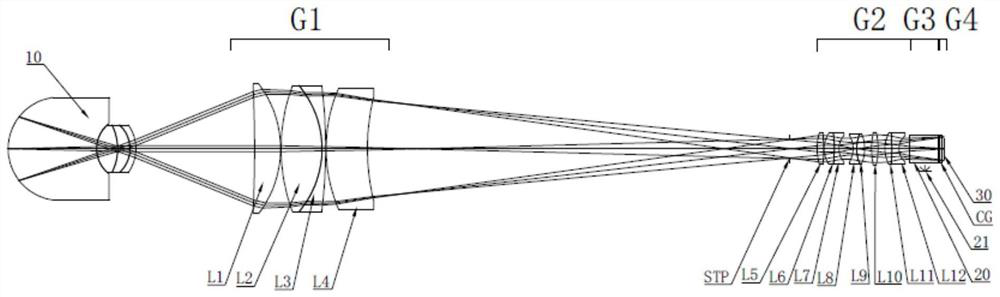
[0069] Embodiment 3: A fundus imaging system, which includes in sequence from the object plane side to the image plane side:
[0070] Eyepiece group G1 with positive dioptric power, imaging objective lens group G2 with positive dioptric power, staring component G3, auxiliary component G4 and sensor 30.
[0071] The eyepiece group G1 includes a first lens L1 with positive power, a second lens L2 with positive power, and a third lens L3 with negative power; wherein, the second lens L2 and the third lens L3 are cemented.
[0072] The imaging objective lens group G2 includes a fourth lens L4 with positive power, a fifth lens L5 with positive power, a sixth lens L6 with negative power, and a seventh lens L7 with negative power, with positive power The eighth lens L8 with a positive refractive power, the ninth lens L9 with a positive refractive power, the tenth lens L10 with a positive refractive power, and the eleventh lens L11 with a negative refractive power; wherein, the fifth l...
PUM
 Abstract
Description
Claims
Application Information
 - R&D Engineer
- R&D Manager
- IP Professional
- Industry Leading Data Capabilities
- Powerful AI technology
- Patent DNA Extraction
Browse by: Latest US Patents, China's latest patents, Technical Efficacy Thesaurus, Application Domain, Technology Topic, Popular Technical Reports.
© 2024 PatSnap. All rights reserved.Legal|Privacy policy|Modern Slavery Act Transparency Statement|Sitemap|About US| Contact US: help@patsnap.com