A wireless power supply system for motor rotor
A wireless power supply and motor rotor technology, applied in control systems, AC motor control, circuits, etc., can solve problems such as affecting the safety and reliability of the motor, limiting the application environment of the motor, easily generating sparks and dust, etc. The effect of improving energy utilization and meeting work demands
- Summary
- Abstract
- Description
- Claims
- Application Information
AI Technical Summary
Problems solved by technology
Method used
Image

Examples
Embodiment 1
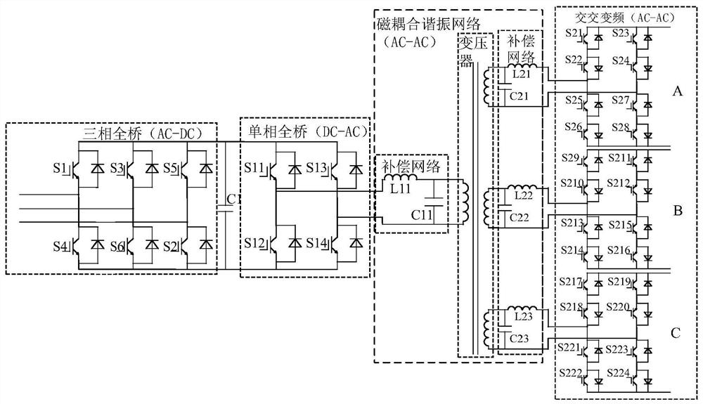
[0054] Embodiment 1 The compensation network is a parallel compensation structure
[0055] The primary-side compensation network and the three secondary-side compensation networks each include a compensation capacitor and a compensation inductor.
[0056] Such as figure 2 As shown, in the primary side compensation network, the compensation capacitor L11 is connected in parallel at both ends of the resolver primary side winding, and the compensation inductor L11 is connected in series with the resolver primary side winding at the midpoint of the two bridge arms of the unidirectional full bridge.
[0057] In the three secondary side compensation networks, each compensation capacitor (C21, C22 or C23) is connected in parallel across the resolver secondary side winding, and the compensation inductor (L21, L22 or L23) is connected in series with the resolver secondary side winding Afterwards, it is connected with the AC-AC frequency conversion circuit of the corresponding phase. ...
Embodiment 2
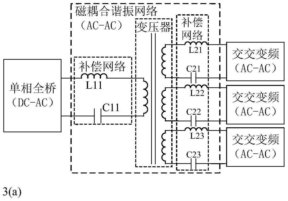
[0059] Embodiment 2 The compensation network is a series compensation network
[0060] The primary-side compensation network and the three secondary-side compensation networks each include a compensation capacitor and a compensation inductor connected in series with the compensation capacitor.
[0061] Such as image 3 As shown in (a), in the primary-side compensation network, the compensation inductor L11, the resolver primary-side winding and the compensation capacitor C11 are serially connected in series and connected to the unidirectional full bridge.
[0062] In the three secondary side compensation networks, the compensation inductor (L21, L22 or L23), the resolver secondary side winding and the compensation capacitor (C21, C22 or C23) are serially connected in series and connected to the AC / AC frequency conversion circuit of the corresponding phase.
[0063] When the working frequency is equal to the resonant frequency, the resonant network is in the full resonant stat...
Embodiment 3
[0064] Embodiment 3 The compensation network is an LCC compensation structure
[0065] Each of the primary side compensation network and the three secondary side compensation networks includes a compensation inductor and two compensation capacitors. The two compensation capacitors are respectively the first compensation capacitor and the second compensation capacitor.
[0066] Such as image 3 As shown in (b), in the primary side compensation network, the first compensation capacitor C11 is connected in parallel at both ends of the resolver primary winding, and the compensation inductance L11, the resolver primary winding and the second compensation capacitor C12 are connected in series with the unidirectional full bridge connected.
[0067] In the three secondary side compensation networks, each first compensation capacitor (C21, C23 or C25) is connected in parallel at both ends of the secondary side winding of the resolver, and the compensation inductor (L21, L22 or L23), ...
PUM
 Abstract
Description
Claims
Application Information
 - R&D
- Intellectual Property
- Life Sciences
- Materials
- Tech Scout
- Unparalleled Data Quality
- Higher Quality Content
- 60% Fewer Hallucinations
Browse by: Latest US Patents, China's latest patents, Technical Efficacy Thesaurus, Application Domain, Technology Topic, Popular Technical Reports.
© 2025 PatSnap. All rights reserved.Legal|Privacy policy|Modern Slavery Act Transparency Statement|Sitemap|About US| Contact US: help@patsnap.com