
Low-frequency radiation unit and base station antenna

A radiation unit and low-frequency technology, applied in the field of low-frequency radiation units and base station antennas, can solve problems such as inconvenience, deterioration of radiation performance, and large size

Pending Publication Date: 2020-10-23
MOBILE ANTENNA TECH SHENZHEN +5
View PDF0 Cites 10 Cited by
  • Summary
  • Abstract
  • Description
  • Claims
  • Application Information

AI Technical Summary

Problems solved by technology

[0003] Due to the shortage of site resources, the above-mentioned multi-frequency multi-system antenna must be miniaturized, and one antenna can realize all frequency bands, and the size cannot be greatly increased
However, there are difficulties in the implementation of the above-mentioned antennas. There are serious coupling interferences between radiating units in different frequency bands, which will cause deterioration of radiation performance and seriously affect network performance. The most obvious impact is the interference of low-frequency radiating units on high-frequency radiation performance.
The existing technology mostly uses cross oscillators for nested arrays, but there are problems such as large size and complicated feeding, and the cost is high
[0004] In summary, there are obviously inconveniences and defects in the actual use of the prior art, so it is necessary to improve it.

Method used


Image

  • Low-frequency radiation unit and base station antenna
  • Low-frequency radiation unit and base station antenna
  • Low-frequency radiation unit and base station antenna

Examples


Embodiment Construction

[0039] In order to make the object, technical solution and advantages of the present invention clearer, the present invention will be described in further detail below in conjunction with the accompanying drawings and embodiments. It should be understood that the specific embodiments described here are only used to explain the present invention, not to limit the present invention.

[0040] It should be noted that references in this specification to "one embodiment", "embodiment", "example embodiment" and the like mean that the described embodiment may include specific features, structures or characteristics, but not every Embodiments must include those specific features, structures or characteristics. Furthermore, such expressions are not referring to the same embodiment. Further, when specific features, structures or characteristics are described in conjunction with an embodiment, whether or not there is an explicit description, it has been indicated that it is within the kn...


PUM


Abstract

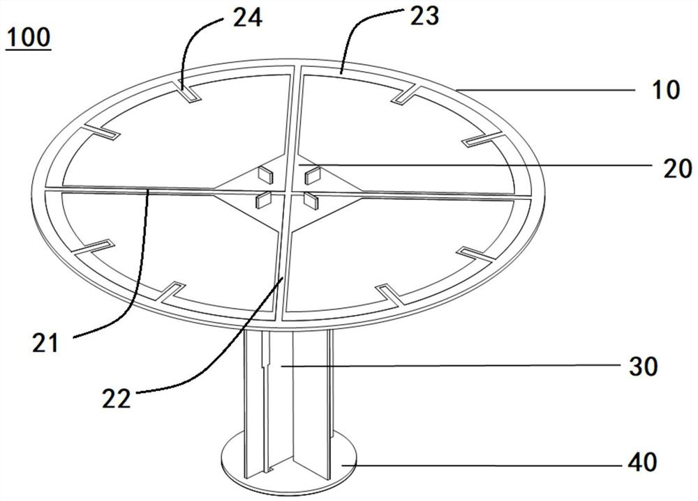
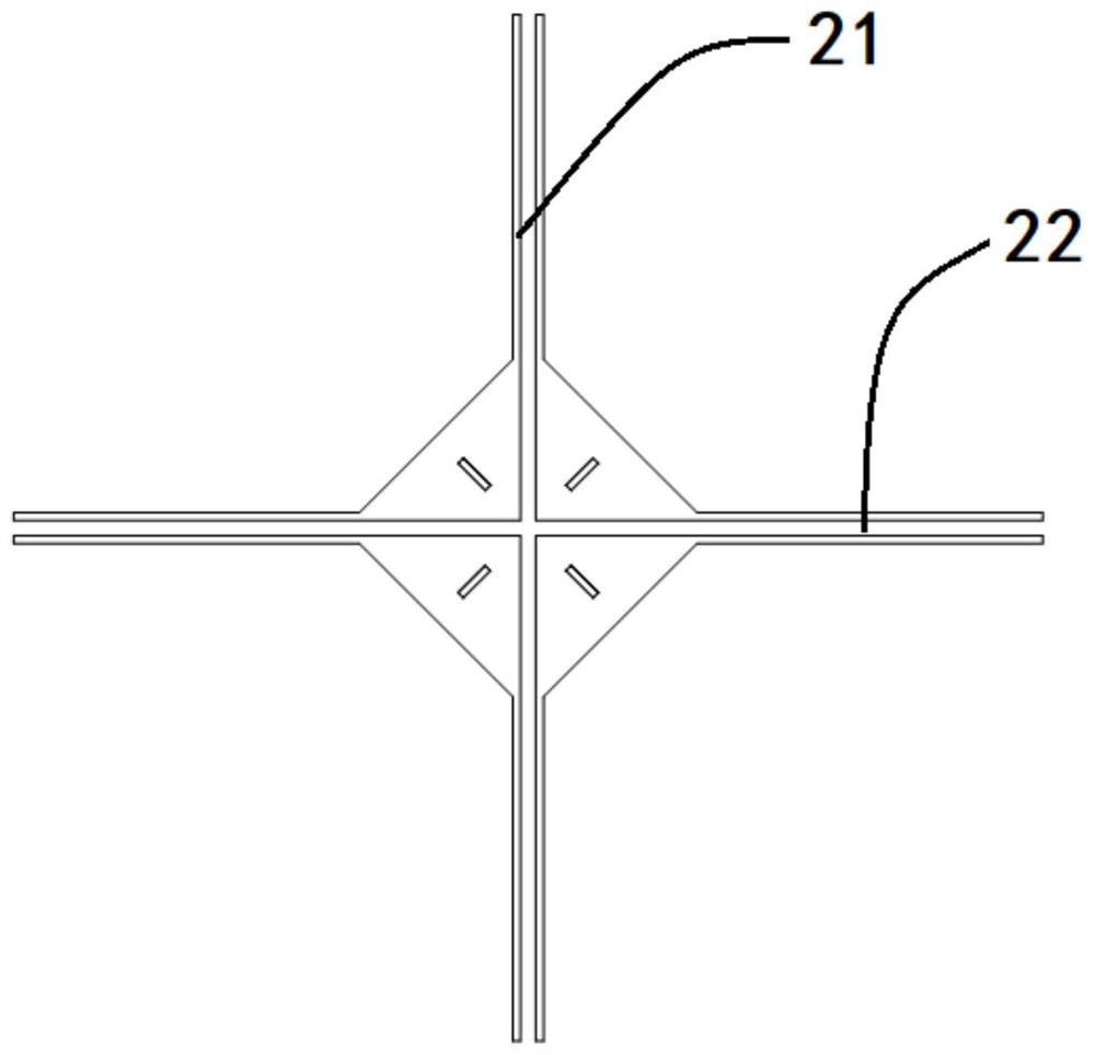
The invention provides a low-frequency radiation unit. The low-frequency radiation unit comprises a dielectric substrate, a radiator and a feed balun, wherein the radiator comprises two dipoles whichare orthogonally distributed, radiation arms of the two dipoles are respectively composed of a vertical line and a horizontal line and jointly form a cross-shaped line, the tail ends of the vertical line and the horizontal line are connected through an arc line, and a plurality of sections of bent lines are arranged in the middle of the arc line; and the feed balun is of an orthogonal structure, the bottom of the feed balun is connected with a feed network, and the top of the feed balun is connected with the radiator. The invention also provides a base station antenna. The base station antennais formed by nesting and inserting a plurality of low-frequency radiation units into the middles of a plurality of high-frequency radiation units. Therefore, the low-frequency radiation unit has a filtering function, the influence of the low-frequency radiation unit on the high-frequency radiation performance can be effectively reduced when the high-frequency antenna and the low-frequency antennaare nested to form an array, and the miniaturization of the antenna size can be realized.

Description

technical field [0001] The invention relates to the technical field of wireless communication, in particular to a low-frequency radiation unit and a base station antenna. Background technique [0002] With the rapid development of wireless communications, the number of spectrums continues to increase, and the scale and number of base stations continue to increase. Problems such as difficult sites and inconvenient installation are becoming increasingly apparent. As the key equipment for wireless access, the base station antenna has multi-frequency multi-system and miniaturization as its main development direction. The low-frequency band of the multi-frequency antenna may include the GSM900 frequency band, which operates at 880-960MHz, and the low-frequency band may also include the 800M frequency band at 790-880MHz, and the 700M frequency band at 694-790Mhz. The high frequency band of the multi-frequency antenna may include the GSM1800 frequency band operating at 1710-1880MH...

Claims


Application Information

Patent Timeline
Patent Type & Authority Applications(China)
IPC IPC(8): H01Q1/38H01Q1/50H01Q1/24H01Q1/52H01Q9/18H01Q15/00H01Q19/10H01Q21/00H01Q21/06H01Q21/24H01Q21/30
CPCH01Q1/38H01Q1/50H01Q9/18H01Q1/521H01Q15/0053H01Q21/0006H01Q21/30H01Q21/062H01Q19/10H01Q21/24H01Q1/246
Inventor 邱小凯江峰邬烈锋梁小健孔唯同
Owner MOBILE ANTENNA TECH SHENZHEN
Learn More