


Quick Research
Generate reliable direction feasibility study reports for your R&D in just a few steps.

Technical Q&A
Discover and master advanced knowledge NOW. Basics, ideas, possibilities, all at once.

Find Solutions
As an expert in R&D theories, this can generate solutions to your technical problems instantly.

Evaluate Feasibility
Analyze your overall solution with one click, know your potential R&D risks in advance.

Monitor Landscape
Get weekly tech updates, stay abreast of the latest tech innovations and key insights.
Circulating drying device based on biomass energy for material processing
A technology of biomass energy and drying equipment, which is applied in the direction of biomass drying, granular material drying, drying, etc.
- Summary
- Abstract
- Description
- Claims
- Application Information
AI Technical Summary
Problems solved by technology
Method used
Image

Examples
Embodiment 1
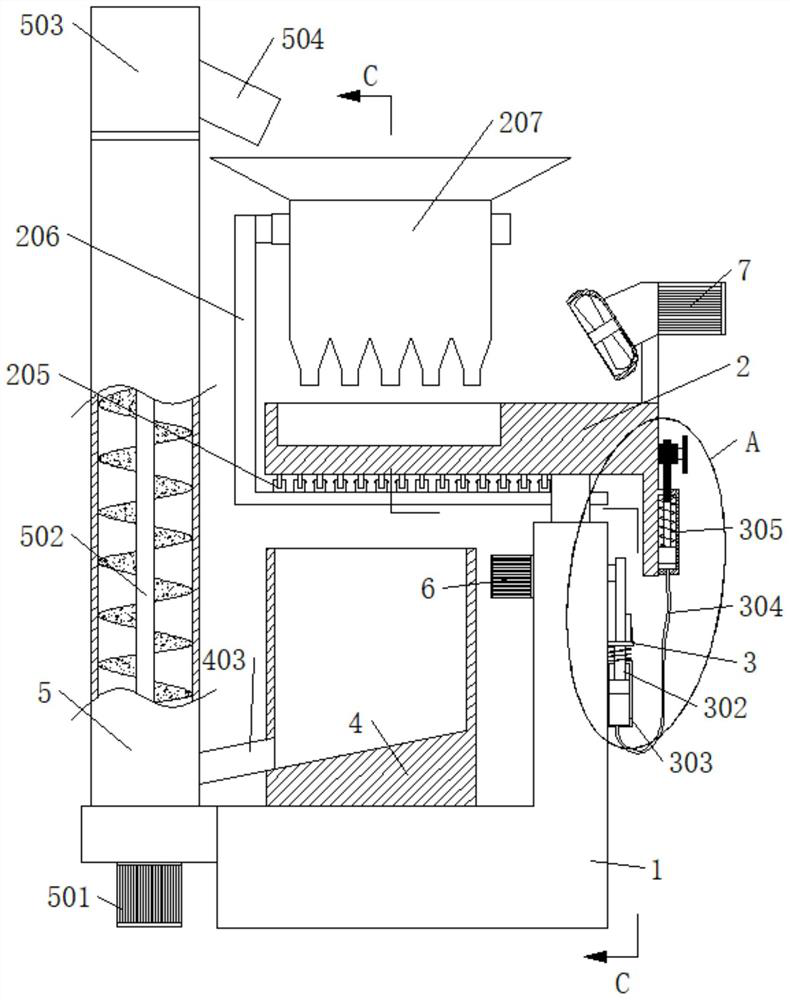
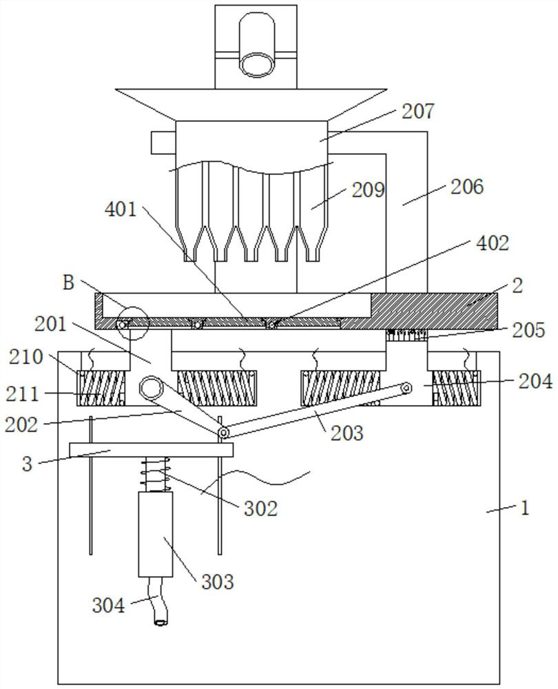
[0028] refer to Figure 1-5 , a circulation drying device based on biomass material processing, including a base 1, a drying panel 2, a feeding box 207, a transfer box 4, and a feeding box 5; wherein, the feeding box 207 is located above the drying panel 2, The bottom of the drying panel 2 is rotatably connected with a plurality of baffle plates 401, and the transfer box 4 is located below the drying panel 2; The feeding box 207 bottom is connected with a plurality of feeding pipes 209, the present invention is by putting material into feeding box 207, drives feeding box 207 and drying panel 2 to keep rocking in the opposite direction by the first driving part, thereby makes the feeding box 207 The material is laid flat on the drying panel 2, and the second drive unit drives a plurality of baffle plates 401 to fit and separate from the drying panel 2 for conversion, so that the material baffle plates 401 are turned over intermittently. When the material baffle plates 401 When...
Embodiment 2
[0030] see Figure 1-5, this implementation shared a specific embodiment of the first driving part, which includes the first slider 201 and the second slider 204, the side wall of the base 1 is provided with a through groove 210, the first slider 201 and the second slider The blocks 204 are all slidably connected in the through groove 210, the upper end of the first slider 201 is fixedly connected with the drying panel 2, the upper end of the second slider 204 is fixedly connected with a bracket 206, and the feeding box 207 is fixedly connected with the upper end of the bracket 206. The first motor 6 is installed on the slider 201, the output end of the first motor 6 is connected with the first connecting rod 202, the first connecting rod 202 is connected to the first slider 201 in rotation, and the second slider 204 is connected in rotation with The second connecting rod 203, the end of the second connecting rod 203 away from the second slider 204 is rotationally connected wi...
Embodiment 3
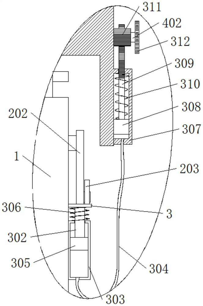
[0032] see Figure 1-5 , this implementation shared a specific embodiment of the second driving part, which includes a slide plate 3 slidably connected to the side wall of the base 1, the slide plate 3 is located below the first connecting rod 202, and is connected to the first connecting rod 202 On the contrary, the side wall of the base 1 is fixedly connected with the first sealed barrel 303, the first sealed barrel 303 is connected with the first piston 305 in a sealed and sliding manner, the first piston 305 is fixedly connected with the first push rod 302, and the upper end of the first push rod 302 It is fixedly connected with the slide plate 3, the drying panel 2 is rotatably connected with a rotating shaft 402, the material retaining plate 401 is fixedly connected with the rotating shaft 402, the extension end of the rotating shaft 402 passes through the side wall of the drying panel 2, and the rotating shaft 402 is fixedly connected with a gear 311, the side wall of t...
PUM
 Abstract
Description
Claims
Application Information
 - R&D Engineer
- R&D Manager
- IP Professional
- Industry Leading Data Capabilities
- Powerful AI technology
- Patent DNA Extraction
Browse by: Latest US Patents, China's latest patents, Technical Efficacy Thesaurus, Application Domain, Technology Topic, Popular Technical Reports.
© 2024 PatSnap. All rights reserved.Legal|Privacy policy|Modern Slavery Act Transparency Statement|Sitemap|About US| Contact US: help@patsnap.com