Circulating drying device for biomass energy material processing

A technology of biomass energy and drying device, which is used in biomass drying, granular material drying, drying and other directions

Inactive Publication Date: 2021-11-05
门亮亮
View PDF9 Cites 0 Cited by
  • Summary
  • Abstract
  • Description
  • Claims
  • Application Information

AI Technical Summary

Problems solved by technology

[0005] In the process of preparing biomass solid fuel, when using a flat die pellet mill to prepare biomass solid fuel, in order to avoid blockage of the flat die pellet mill during the pelletizing process, there is usually some moisture remaining in the raw material, so After granulation and molding, the biomass fuel particles are usually dried to reduce the residual moisture inside the biomass fuel particles and facilitate subsequent transportation. However, the existing drying devices cannot perform automatic cycle drying. Therefore, we propose a circulation drying device for biomass energy material processing to improve the drying effect

Method used


Image

  • Circulating drying device for biomass energy material processing
  • Circulating drying device for biomass energy material processing
  • Circulating drying device for biomass energy material processing

Examples


Embodiment 1

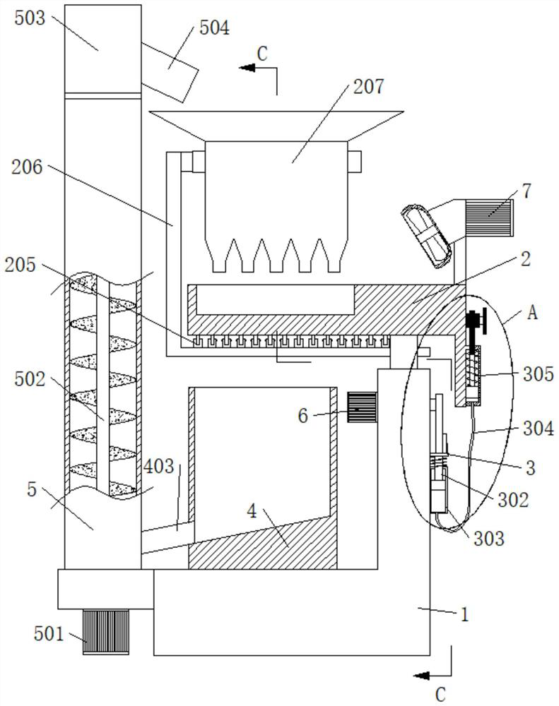
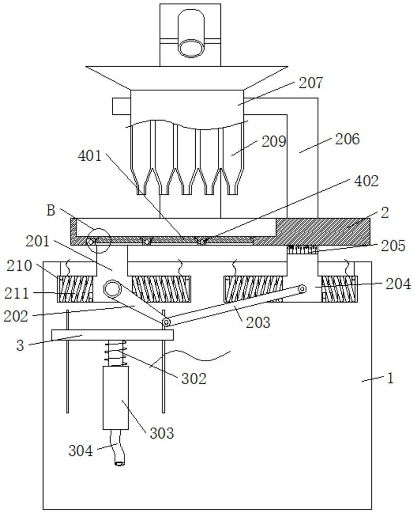
[0028] refer to Figure 1-5 , a circulation drying device for biomass material processing, comprising a base 1, a drying panel 2, a feeding box 207, a transfer box 4, and a feeding box 5; wherein, the feeding box 207 is located above the drying panel 2, and the drying The bottom of the dry panel 2 is rotatably connected with a plurality of baffle plates 401, and the transfer box 4 is located below the drying panel 2; the transfer box 4 is connected to the feeding box 5, and the feeding box 5 is used to transport materials into the feeding box 207; The bottom of the feeding box 207 is connected with a plurality of feeding pipes 209. The present invention puts materials into the feeding box 207 and drives the feeding box 207 to shake in the opposite direction with the drying panel 2 through the first driving part, so that the materials in the feeding box 207 The material is laid flat on the drying panel 2, and the second driving part drives a plurality of baffle plates 401 to fi...

Embodiment 2

[0030] see Figure 1-5, this implementation shared a specific embodiment of the first driving part, which includes the first slider 201 and the second slider 204, the side wall of the base 1 is provided with a through groove 210, the first slider 201 and the second slider The blocks 204 are all slidably connected in the through groove 210, the upper end of the first slider 201 is fixedly connected with the drying panel 2, the upper end of the second slider 204 is fixedly connected with a bracket 206, and the feeding box 207 is fixedly connected with the upper end of the bracket 206. The first motor 6 is installed on the slider 201, the output end of the first motor 6 is connected with the first connecting rod 202, the first connecting rod 202 is connected to the first slider 201 in rotation, and the second slider 204 is connected in rotation with The second connecting rod 203, the end of the second connecting rod 203 away from the second slider 204 is rotationally connected wi...

Embodiment 3

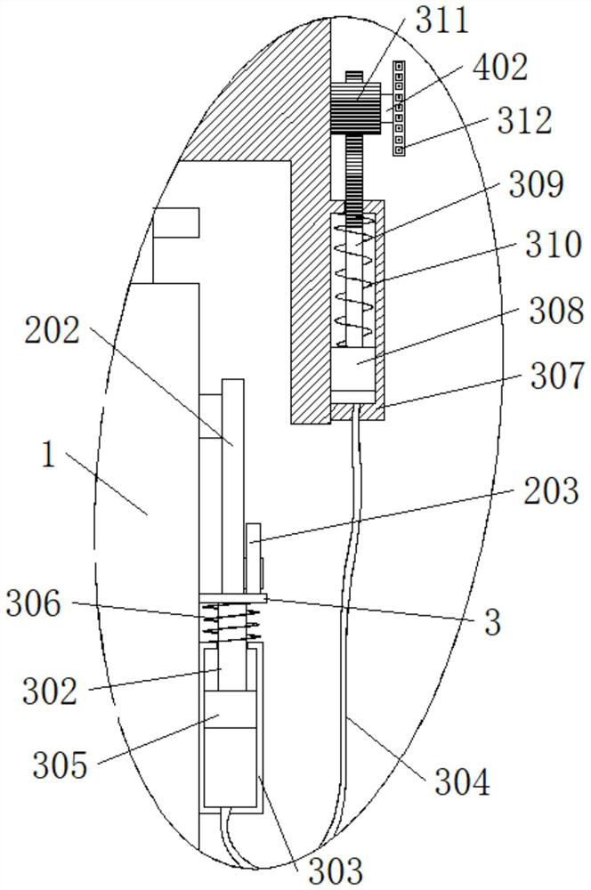
[0032] see Figure 1-5 , this implementation shared a specific embodiment of the second driving part, which includes a slide plate 3 slidably connected to the side wall of the base 1, the slide plate 3 is located below the first connecting rod 202, and is connected to the first connecting rod 202 On the contrary, the side wall of the base 1 is fixedly connected with the first sealed barrel 303, the first sealed barrel 303 is connected with the first piston 305 in a sealed and sliding manner, the first piston 305 is fixedly connected with the first push rod 302, and the upper end of the first push rod 302 It is fixedly connected with the slide plate 3, the drying panel 2 is rotatably connected with a rotating shaft 402, the material retaining plate 401 is fixedly connected with the rotating shaft 402, the extension end of the rotating shaft 402 passes through the side wall of the drying panel 2, and the rotating shaft 402 is fixedly connected with a gear 311, the side wall of t...


PUM


Abstract

The invention discloses a circulating drying device for biomass energy material processing, and belongs to the field of biomass energy. The circulating drying device for biomass energy material processing comprises a base, a drying panel, a feeding box, a transfer box and a conveying box, The feeding box is located above the drying panel, the bottom of the drying panel is rotationally connected with a plurality of material blocking plates, and the transfer box is located below the drying panel; the transfer box communicates with the conveying box, and the conveying box is used for conveying materials into the feeding box; and the device further comprises a first driving part, and a second driving part, and the first driving part is used for driving the feeding box and the drying panel to shake in the opposite directions. The second driving part is used for driving the plurality of material blocking plates to be attached to and separated from the drying panel for conversion; and during feeding, the multiple material blocking plates are turned over intermittently, so that material particles can be dried circularly.

Description

[0001] This application is a divisional application, the original patent number is: 202010741755.2, the application date is July 29, 2020, and the title of the invention is: a circulation drying device for processing biomass-based materials. technical field [0002] The invention relates to the technical field of biomass energy, in particular to a circulation drying device for processing biomass energy materials. Background technique [0003] New energy generally refers to renewable energy that is developed and utilized on the basis of new technologies, including solar energy, biomass energy, water energy, wind energy, geothermal energy, wave energy, ocean current energy, and tidal energy, as well as the energy between the ocean surface and the deep layer. Thermal cycle, etc.; in addition, there are hydrogen energy, biogas, alcohol, methanol, etc. With the limitation of conventional energy sources and the increasingly prominent environmental problems, new energy sources with ...

Claims


Application Information

Patent Timeline
Patent Type & Authority Applications(China)
IPC IPC(8): F26B17/00F26B25/00F26B25/04
CPCF26B17/00F26B25/002F26B25/04F26B2200/02F26B2200/08
Inventor 不公告发明人
Owner 门亮亮
Why Eureka
Try Eureka