
Fluid control equipment for square cabin

A technology for controlling equipment and fluids, which is applied in the field of shelters, and can solve the problems of too fast spring reset, insufficient time for washing hands, troublesome opening, etc.

Active Publication Date: 2020-10-23
衡阳泰豪通信车辆有限公司
View PDF6 Cites 4 Cited by
  • Summary
  • Abstract
  • Description
  • Claims
  • Application Information

AI Technical Summary

Problems solved by technology

[0005] 1. Due to the field work in the existing technology, there is a shortage of water resources, and the only precious water resources must be used rationally. For example, when washing hands, the faucet is often turned on too large, resulting in waste of water resources, and slowly a trace It is very troublesome to open the wire. Correspondingly, if the tap flow is too small for drinking water demand, it will waste time
[0006] 2. The water resources equipment in the shelter of the prior art, such as the faucet, often can only realize single-dimensional drive, such as linear drive and rotation, when it is opened, resulting in a single function
[0007] 3. The water resource equipment in the shelter of the prior art, such as the faucet, can realize the delay function, but only rely on the spring for the upward delay reset, resulting in the spring reset too fast, and it is impossible to reserve enough time to wash hands
[0008] 4. The shelter water resources equipment in the prior art, such as faucet, partly includes additional diversion channels. However, the additional diversion channels often require multiple conduits, or directly set vertical channels in the valve housing. However, the vertical channels are processed in the valve housing. Passage is very difficult
[0009] 5. The water resources equipment in the shelters of the prior art, such as faucets, are often set in the air, and because the bottom surface of the valve is not flat, it is difficult to support

Method used


Image

  • Fluid control equipment for square cabin
  • Fluid control equipment for square cabin
  • Fluid control equipment for square cabin

Examples


Embodiment Construction

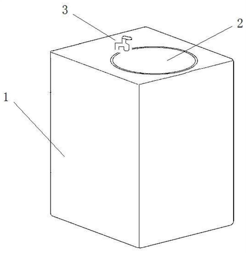
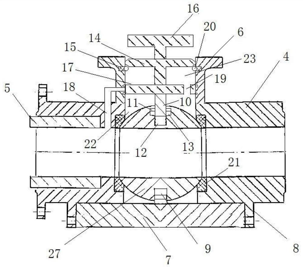
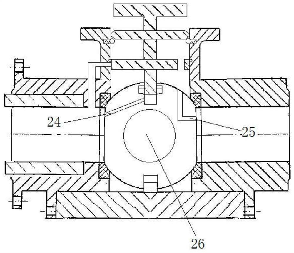
[0040] As shown in the figure: a fluid control equipment for a shelter, including a valve body, a pipe joint, a valve neck, a support block, hanging lugs, a lower valve shaft, a first T-shaped piece, a second T-shaped piece, and a third T-shaped piece parts, lower cavity, middle cavity, upper cavity, clamping block, chute, avoidance groove, avoidance ball, small flow conduit, small hole, sealing seat, valve ball; wherein the first T-shaped member includes an upper valve shaft and a closed plate; wherein the inside of the valve ball is provided with a pressure maintaining channel, a small flow discharge channel, and a through hole;

[0041] Wherein the left side of the valve body is provided with the pipe joint, and the outer wall of the pipe joint is provided with threads to connect with the internal thread provided on the left side of the valve body. On the right side of the pipe joint, the valve The upper surface of the valve body on the left side of the ball is provided wit...


PUM


Abstract

The invention discloses fluid control equipment for a square cabin. The fluid control equipment comprises a valve body, a pipe joint, a valve neck, a support block, a lug, a lower valve shaft, a firstT-shaped part, a second T-shaped part, a third T-shaped part, a lower cavity, a middle cavity, an upper cavity, a clamping block, a sliding chute, an avoiding groove, an avoiding ball, a small-flow conduit, a small hole, a sealing base and a valve ball, wherein the first T-shaped part comprises an upper valve shaft and an enclosing plate; and a pressure-keeping channel, a small-flow draining channel and a pass-through hole are formed inside the valve ball.

Description

technical field [0001] The invention relates to the field of shelters, in particular to fluid control equipment for shelters. Background technique [0002] The shelter is an important equipment that can be used in military, medical, communication and other fields. The shelter is suitable for use in field operations. It is widely used in various fields, such as mobile command systems, communications, medical care, logistics support, etc. It is one of the important equipment of modern mobile forces; at the same time, the shelter is also used in special civilian vehicles, such as emergency communication vehicles, power station vehicles, large equipment loading vehicles, etc. [0003] Various equipment will also be adapted in the shelter, such as hydraulic equipment, photography beds, communication equipment, etc. Among them, hydraulic equipment, such as water resource equipment, is widely used, such as the need for cleaning the operating table, the need for domestic water, and...

Claims


Application Information

Patent Timeline
Patent Type & Authority Applications(China)
IPC IPC(8): F16K5/06F16K5/08F16K5/10F16K5/12F16K21/02F16K27/06
CPCF16K5/0647F16K5/08F16K5/10F16K5/12F16K21/02F16K27/067
Inventor 冯文明高国清崔化刚海效成颜剑费俭平贺才进
Owner 衡阳泰豪通信车辆有限公司
Learn More