
Construction method for superimposing and connecting wallboards in steel bar lap joint area

A technology of lap connection and wall panel, applied in the direction of walls, structural elements, building components, etc., can solve the problems of high technical requirements, difficulty, and complex construction.

Inactive Publication Date: 2020-10-23
唐山昱邦新型建材有限公司
View PDF12 Cites 3 Cited by
  • Summary
  • Abstract
  • Description
  • Claims
  • Application Information

AI Technical Summary

Problems solved by technology

In the construction process of the above-mentioned sleeve and grout anchor connection method, the vertical steel bars need to correspond to the connecting sleeve one by one, and then grouting. This connection method uses a lot of equipment and tools, the construction process is complicated, and the construction technology requirements are high. , due to the high technical requirements of grouting, complex operation, and no feasible detection method, it is prone to construction quality problems
Since the strength of the grouting material will be lost when it is constructed at low temperature, the grouting material is currently only constructed at a temperature of -5°C and above. When the temperature is lower than -5°C, corresponding winter construction measures need to be taken to increase construction costs.
[0003] At present, in the construction of prefabricated shear walls, two-way laminated shear wall connection technology is also used. However, when this construction method is adopted, the wall panel components with door and window openings and the post-casting sections between wall panel components need to be supported with formwork. In addition, the binding form of the concealed column steel bars is relatively complicated, and the construction speed is slow
[0004] Most of these technologies are relatively complicated in construction, relatively high in project cost, and have certain difficulties in the promotion process, so they cannot be widely applied in the industry.

Method used


Image

  • Construction method for superimposing and connecting wallboards in steel bar lap joint area
  • Construction method for superimposing and connecting wallboards in steel bar lap joint area
  • Construction method for superimposing and connecting wallboards in steel bar lap joint area

Examples


Embodiment Construction

[0029] The present invention will be further described below in conjunction with the examples, the purpose is only to better understand the contents of the present invention, therefore, the examples given do not limit the protection scope of the present invention.

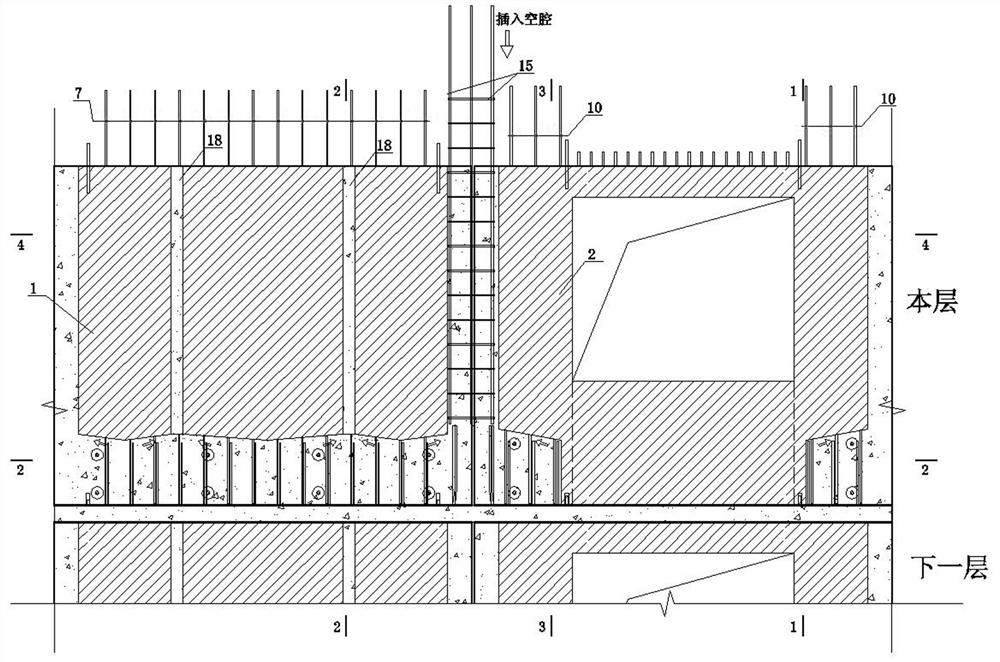
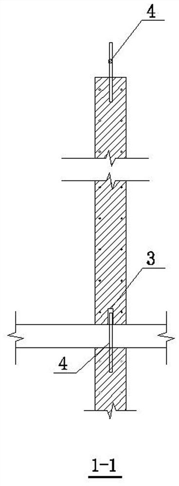
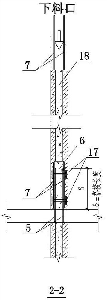
[0030] see Figure 1 to Figure 6 , a construction method for superimposing and connecting wallboards in the overlapping connection area of ​​steel bars is carried out according to the following steps:

[0031] (1) When installing wall panel 1 without door and window openings and wall panel components 2 with door and window openings on this floor, match the two positioning holes 3 reserved at the bottom of the components with the two positioning steel bars 4 embedded in the lower layer one by one, and then drop and install them.

[0032] (2) In the wall panel member 1 without door and window openings, the vertically distributed steel bars 5 of the next layer of wall panels extend into the distributed overlapping cav...


PUM


Abstract

The invention relates to the technical field of prefabricated building construction, in particular to a construction method for superimposing and connecting wallboards in a steel bar lap joint area. An overall cavity is reserved in the lap joint area of vertical steel bars, according to different types of components, a pouring hole is reserved at the top of the cavity, a tie part of an anti-expansion mold is embedded in the side wall of the cavity, and a positioning hole is reserved at the bottom of a component. The wallboard component is different from wallboards needing to be filled with high-strength grouting materials through sleeve grouting, grout anchor connection and the like that require vertical steel bars correspond in a one-to-one mode, and is also different from wallboards withlap connection at the bottom. The wallboard overcomes the problems of consuming a lot of installation time and secondary grouting during the sleeve connection installation process, and also overcomesthe problem of erecting reinforcement templates twice through a lap joint technology the safe and reliable connection is achieved, installation is accurate and fast, and the construction cost is reduced through the safe, fast and efficient connection technology.

Description

technical field [0001] The invention relates to the technical field of prefabricated building construction, in particular to a construction method for superimposed and connected wall panels in overlapping joints of steel bars. Background technique [0002] In the construction process of prefabricated shear wall structures, the vertical reinforcement of prefabricated wall panel components is usually connected by sleeve grouting connection, restraint grout anchor connection and double-layer laminated connection. In the construction process of the above-mentioned sleeve and grout anchor connection method, the vertical steel bars need to correspond to the connecting sleeve one by one, and then grouting. This connection method uses a lot of equipment and tools, the construction process is complicated, and the construction technology requirements are high. , due to the high technical requirements of grouting, complex operation, and no feasible detection method, it is prone to cons...

Claims


Application Information

Patent Timeline
IPC IPC(8): E04B2/00E04C5/01
CPCE04B2/00E04C5/01
Inventor 李哲龙李晓亮
Owner 唐山昱邦新型建材有限公司
Learn More