
Traction device for pediatric orthopedics department

A traction device and orthopedic technology, applied in non-surgical orthopedic operations, fractures, medical science, etc., can solve the problems of inability to adjust, inability to intuitively know the magnitude of the pulling force during traction, etc.

Active Publication Date: 2020-10-23
SHANDONG UNIV OF TRADITIONAL CHINESE MEDICINE
View PDF16 Cites 0 Cited by
  • Summary
  • Abstract
  • Description
  • Claims
  • Application Information

AI Technical Summary

Problems solved by technology

Existing orthopedic traction frames can only traction both legs of the patient at the same time, which is inconvenient when traction is required for a single leg, and the existing traction devices cannot intuitively know the pulling force during traction. It is not possible to carry out precise pulling force, and most of the existing traction devices are integrated, which is not only bulky and inconvenient for handling and transportation, but also inconvenient to adjust, especially for children, whose heights vary greatly, and Some traction devices cannot be adjusted according to children of different heights, which is inconvenient during specific use

Method used


Image

  • Traction device for pediatric orthopedics department
  • Traction device for pediatric orthopedics department
  • Traction device for pediatric orthopedics department

Examples


Embodiment 1

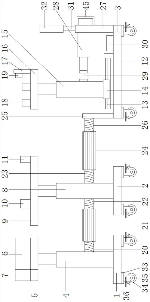
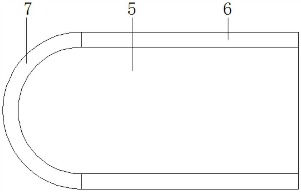
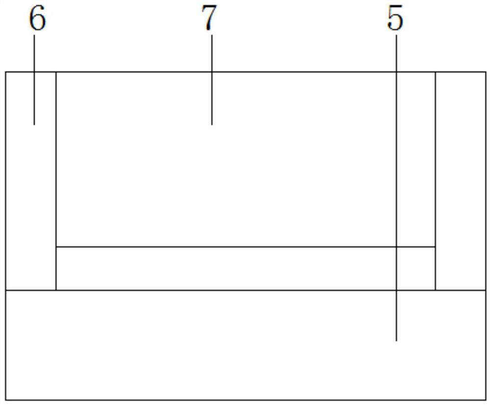
[0039] see Figure 1-9, a pediatric orthopedic traction device according to an embodiment of the present invention, comprising a first base plate 1, a second base plate 2 and a third base plate 3, the first base plate 1, the second base plate 2 and the third base plate 3 are all A moving assembly is provided, the first bottom plate 1, the second bottom plate 2 and the third bottom plate 3 are arranged in a straight line, the first telescopic cylinder 4 is fixed on the first bottom plate 1, and the first telescopic cylinder 4 is fixed on the first bottom plate 1. The piston rod of the cylinder 4 is fixedly provided with a head support plate 5, and both sides of the upper end of the head support plate 5 are fixedly provided with side plates 6, and the top end of the head support plate 5 is fixedly provided with an arc-shaped plate 7. The second bottom plate 2 is fixedly provided with a second telescopic cylinder 8, and the second telescopic cylinder 8 is fixedly provided with a ...

Embodiment 2

[0042] see figure 1 with 3 , for the mobile assembly, the mobile assembly includes bearings 33, and the four corners of the first bottom plate 1, the second bottom plate 2 and the third bottom plate 3 are fixed with bearings 33, and the bearings 33 are all fixedly provided with wheel support 34, and moving wheel 35 is all installed under described wheel support 34; For wheel support 34, described wheel support 34 one sides are all equipped with pedal type braking device 36; As for the supporting plate 5, a sponge pad is fixedly arranged on the said head supporting plate 5.

[0043] Through the above-mentioned solution of the present invention, the moving wheel 35 can facilitate the movement of the whole device, and the moving wheel 35 can be locked by the pedal brake device 36, and the sponge pad can increase the comfort of the patient's head.

Embodiment 3

[0045] see Figure 4-6 , for the body restraint device 10, the body restraint device 10 includes a first restraint belt 37 and a second restraint belt 38, and the first restraint belt 37 and the second restraint belt 38 are respectively fixed on the body support On both sides of the board 9, the first restraint belt 37 and the second restraint belt 38 are fixed by Velcro bonding; for the thigh restraint device 11, the thigh restraint device 11 includes the third restraint belt 39 and The fourth restraint belt 40, the third restraint belt 39 and the fourth restraint belt 40 are all fixed on the body support plate 9, between the third restraint belt 39 and the corresponding fourth restraint belt 40 Fastened by Velcro.

[0046] Through the above scheme of the present invention, the first restraint belt 37 and the second restraint belt 38 can bind and fix the body of the patient, and the third restraint belt 39 and the fourth restraint belt 40 can fix the thigh root of the patien...


PUM


Abstract

The invention discloses a traction device for the pediatric orthopedics department. The device comprises a first bottom plate, a second bottom plate and a third bottom plate, moving assemblies are arranged below the first bottom plate, the second bottom plate and the third bottom plate correspondingly, the first bottom plate, the second bottom plate and the third bottom plate are arranged linearly, a first telescopic air cylinder is fixedly arranged on the first bottom plate, and a head supporting plate is fixedly arranged on a piston rod of the first telescopic air cylinder. The device has the following beneficial effects: the two legs of a patient can be pulled at the same time, traction can be conducted on the single leg of the patient, the distances among the first bottom plate, the second bottom plate and the third bottom plate can be adjusted, and the bottom plates can be detached, so that the device can be suitable for children with different heights, can be detached to facilitate carrying and transportation, and can detect the magnitude of tension during traction in real time by utilizing a tension sensor and display the magnitude of the tension on a display screen.

Description

technical field [0001] The invention relates to the technical field of children's orthopedics, in particular to a traction device for children's orthopedics. Background technique [0002] At present, the traction device is mainly used for performing orthopedic surgery on the limbs, and can perform lateral and horizontal traction on the patient's limbs during the operation. With the changes of the times and society, the spectrum of orthopedic injuries has undergone significant changes. For example, bone and joint tuberculosis, osteomyelitis, polio and other diseases have decreased significantly, and trauma caused by traffic accidents has increased significantly. Existing orthopedic traction frames can only traction both legs of the patient at the same time, which is inconvenient when traction is required for a single leg, and the existing traction devices cannot intuitively know the pulling force during traction. It is not possible to carry out precise pulling force, and mos...

Claims


Application Information

Patent Timeline
IPC IPC(8): A61F5/045A61F5/37A61G13/12A61B90/14A61B17/02
CPCA61F5/042A61G13/12A61F5/3769A61B90/14A61B17/02
Inventor 薛远亮
Owner SHANDONG UNIV OF TRADITIONAL CHINESE MEDICINE
Learn More