
Interventional medical instrument conveying system smooth in conveying

A technology for medical devices and delivery systems, applied in the field of medical devices, can solve problems such as hindering the push of interventional medical devices, device damage, and delivery jams.

Pending Publication Date: 2020-10-23
HANGZHOU NUOMAO MEDTECH CO LTD
View PDF0 Cites 8 Cited by
  • Summary
  • Abstract
  • Description
  • Claims
  • Application Information

AI Technical Summary

Problems solved by technology

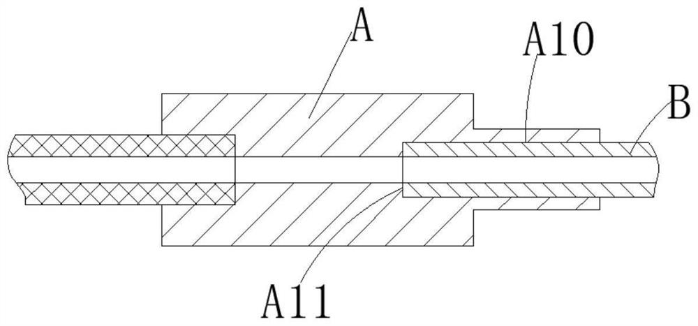
However, in the actual connection and fitting process, on the one hand, the operator tends to overtighten the screw thread so that the distal end surface of the loading tube B and the stepped surface A11 of the stepped hole A10 in the sheath tube seat A are excessively docked, resulting in excessive abutment of the loading tube B. The nozzle at the distal end of B is narrowed, causing the interventional medical device in the loading tube B to pass through the place smoothly, and the transportation is stuck. It may also be caused by the excessive resistance of the interventional medical device when passing through the nozzle at the distal end of the loading tube B. The device is damaged; on the other hand, if the distal end of the loading tube B is not in place with the stepped surface A11 of the stepped hole A10, that is, there is an axial gap between the stepped surface A11 and the distal end of the loading tube B, some barbs will be caused. Structural interventional medical devices get stuck in the gap, hindering the push of the interventional medical device and increasing the risk of barb breakage

Method used


Image

  • Interventional medical instrument conveying system smooth in conveying
  • Interventional medical instrument conveying system smooth in conveying
  • Interventional medical instrument conveying system smooth in conveying

Examples


Embodiment Construction

[0024] The following will clearly and completely describe the technical solutions in the embodiments of the present invention with reference to the accompanying drawings in the embodiments of the present invention. Obviously, the described embodiments are only some, not all, embodiments of the present invention. Based on the embodiments of the present invention, all other embodiments obtained by persons of ordinary skill in the art without making creative efforts belong to the protection scope of the present invention.

[0025] In addition, the following descriptions of the various embodiments refer to the attached drawings to illustrate specific embodiments in which the present invention can be implemented. The directional terms mentioned in the present invention, for example, "upper", "lower", "front", "rear", "left", "right", "inner", "outer", "side", etc., only is to refer to the direction of the attached drawings. Therefore, the direction terms used are for better and mor...


PUM


Abstract

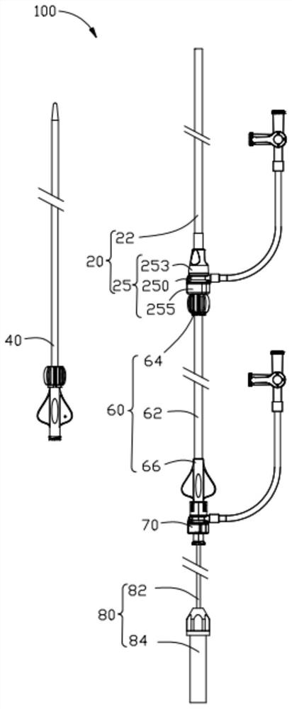
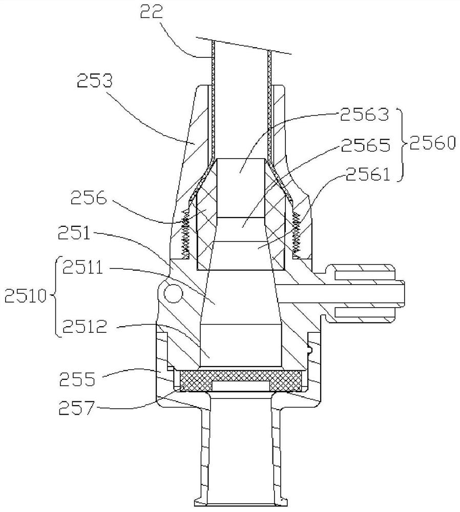
The invention provides an interventional medical instrument conveying system smooth in conveying. The system comprises a conveyor and a loader; the conveyor comprises a conveying sheath tube and a sheath tube seat connected to the near end of the conveying sheath tube; the loader comprises a loading tube, the far end of the loading tube is detachably connected with the sheath tube seat, and a connecting through hole extending in the axial direction of the sheath tube seat is formed in the sheath tube seat so as to achieving communicating between the loading tube with the conveying sheath tube,the connecting through hole comprises a reducing hole section, the hole diameter of the reducing hole section is gradually reduced from the near end to the far end, and the far end face of the loading tube extends into the reducing hole section from the near end of the connecting through hole; and a radial gap is formed between the far end face of the loading tube and the corresponding part of the reducing hole section. The interventional medical instrument conveying system can convey interventional medical instruments smoothly, and the requirement for assembling the loading tube and the sheath tube seat in the system is reduced.

Description

technical field [0001] The invention relates to the technical field of medical instruments, in particular to an interventional medical instrument delivery system with smooth delivery. Background technique [0002] Minimally invasive interventional procedures are becoming more and more widely used in clinical applications. The delivery system of intracavitary interventional medical devices (such as left atrial appendage occluders, vascular plugs, filters, etc.) usually includes conveyors, expanders, loaders, pushers (such as Cable) and other parts, wherein the conveyor includes a delivery sheath and a sheath seat. The delivery sheath and dilator first establish a channel, then withdraw the dilator, put the interventional medical device into the loader through the pusher, then connect the sheath holder and the loader, and introduce the interventional medical device into the delivery sheath through the pusher until Delivery of interventional medical devices to targeted locatio...

Claims


Application Information

Patent Timeline
IPC IPC(8): A61B17/12A61B17/00
CPCA61B17/0057A61B17/12031A61B17/12109A61B17/12122A61B17/12159A61B2017/00575A61B2017/00606A61B2017/00623A61B2017/12054
Inventor 张庭超李阳董壮
Owner HANGZHOU NUOMAO MEDTECH CO LTD
Learn More