


Quick Research
Generate reliable direction feasibility study reports for your R&D in just a few steps.

Technical Q&A
Discover and master advanced knowledge NOW. Basics, ideas, possibilities, all at once.

Find Solutions
As an expert in R&D theories, this can generate solutions to your technical problems instantly.

Evaluate Feasibility
Analyze your overall solution with one click, know your potential R&D risks in advance.

Monitor Landscape
Get weekly tech updates, stay abreast of the latest tech innovations and key insights.
Protection pipe sleeve for water-passing power cable
A power cable and protection tube technology, which is applied in the field of protective tube sleeves for power cables passing through water, can solve the problems of difficulty in finding in time, difficulty in checking the location of damaged points, etc.
- Summary
- Abstract
- Description
- Claims
- Application Information
AI Technical Summary
Problems solved by technology
Method used
Image

Examples
Embodiment 1
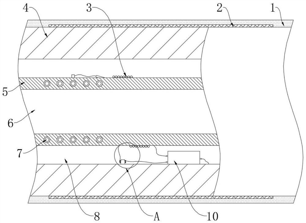
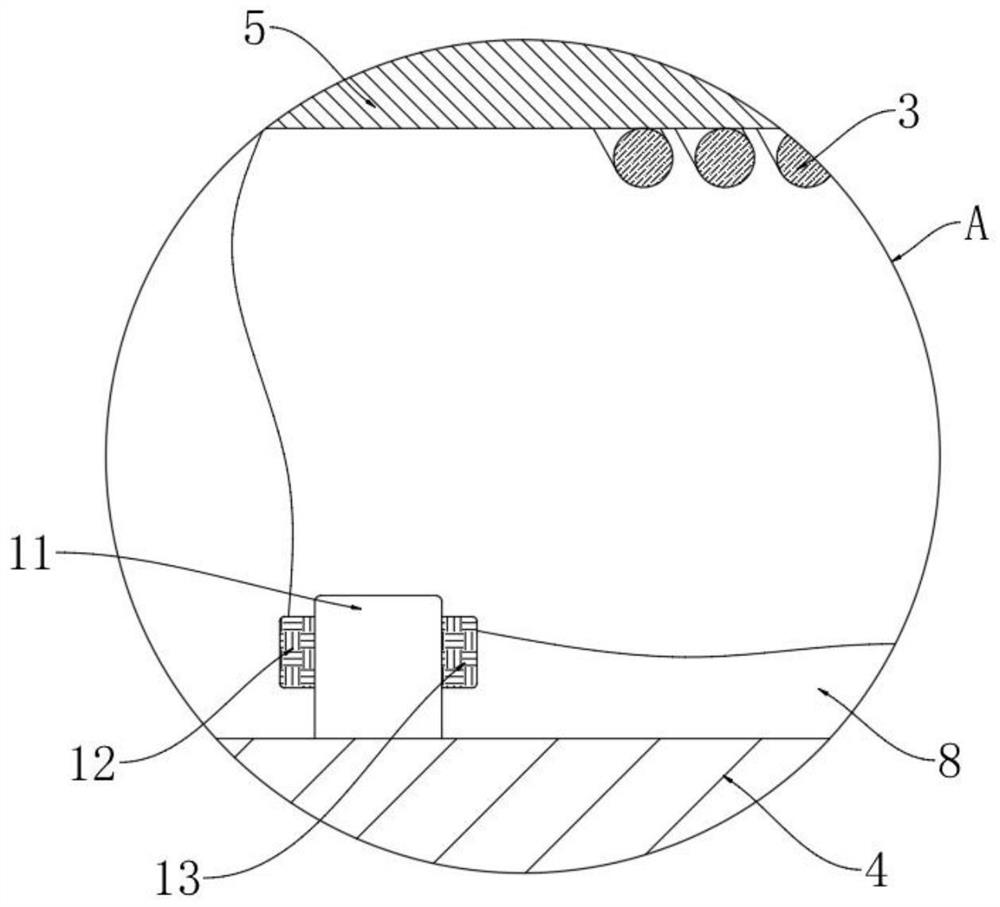
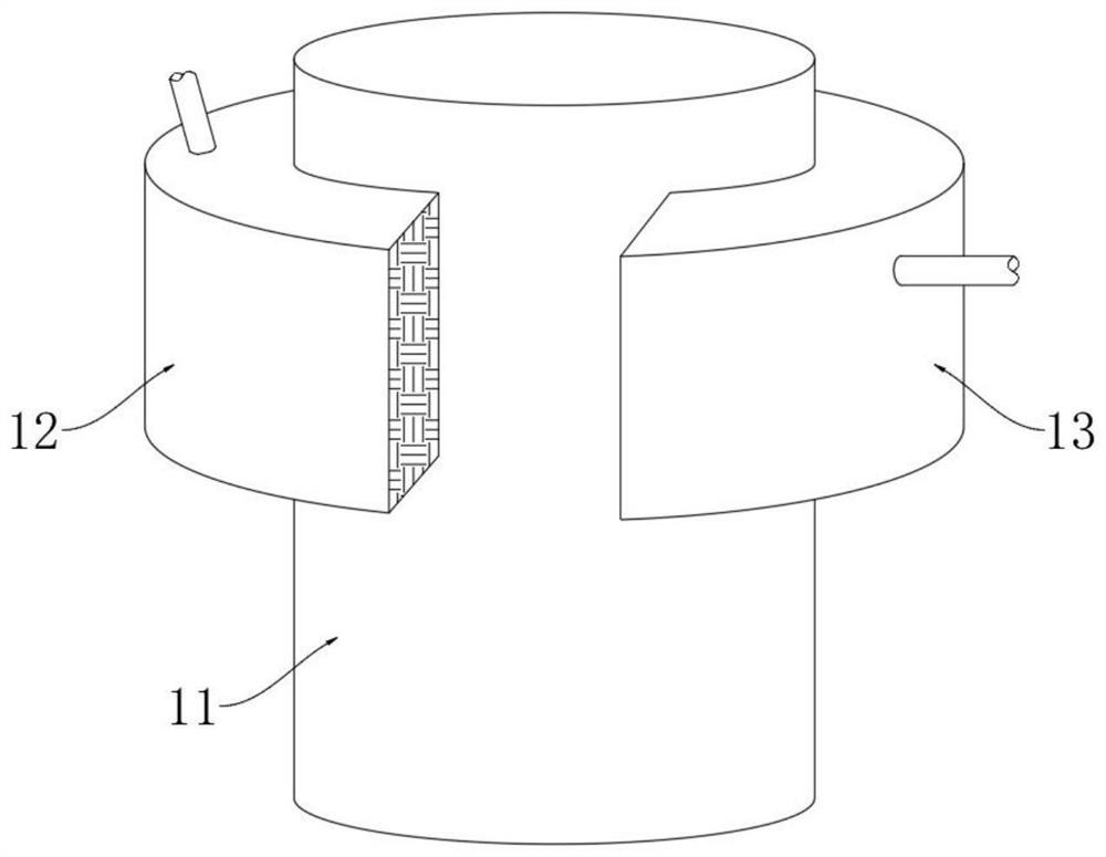
[0025] refer to Figure 1-5 , a kind of protective sleeve for power cables through water, comprising a protective tube 4, the protective tube 4 is covered with a visible layer 1, the visible layer 1 is made of a transparent elastic material, the visible layer 1 and the outer wall of the protective tube 4 There is a luminescent layer 2 between them, the luminescent layer 2 is electroluminescent paint, the protective tube 4 is provided with a wire core 6 with an insulating layer 5, an induction coil 7 is installed in the insulating layer 5, and the insulating layer 5 and the protective tube 4 A water-proof cavity 8 is formed between them, and a short-circuit device and a conduction device are fixedly arranged in the water-proof cavity 8, and a high-resistance ring 3 is set on the outer side of the insulating layer 5, and one end of the high-resistance ring 3 is electrically connected with the induction coil 7, and the high-resistance coil 3 is electrically connected to the induct...
Embodiment 2
[0036] refer to Image 6 , the difference between this embodiment and Embodiment 1 is that: the outer fixed sleeve of the insulating layer 5 is provided with a friction sleeve 9, one end of the friction sleeve 9 is interference fit with a fixed ring 17, and the outer side of the friction sleeve 9 is wound with a A flexible spring 16, and one end of the flexible spring 16 is fixedly connected to the fixed ring 17, and the flexible spring 16 can only move away from the fixed ring 17 when stretched.
[0037]When the present embodiment is in use, the flexible spring 16 can be connected with the induction coil 7, and the flexible spring 16 is on a parallel branch, because the flexible spring 16 has an electrostrictive effect, so when an alternating current flows through the flexible spring 16, the flexible spring 16 The spring 16 will quickly expand and contract, thereby rubbing against the friction sleeve 9 to generate heat;
[0038] It is worth mentioning that when the flexible ...
PUM
 Abstract
Description
Claims
Application Information
 - R&D Engineer
- R&D Manager
- IP Professional
- Industry Leading Data Capabilities
- Powerful AI technology
- Patent DNA Extraction
Browse by: Latest US Patents, China's latest patents, Technical Efficacy Thesaurus, Application Domain, Technology Topic, Popular Technical Reports.
© 2024 PatSnap. All rights reserved.Legal|Privacy policy|Modern Slavery Act Transparency Statement|Sitemap|About US| Contact US: help@patsnap.com