
A common optical path phase-shift digital holographic microscopic measurement device

A digital holographic microscope and measurement device technology, applied in the field of digital holography, can solve problems such as unfavorable phase reconstruction accuracy and complex phase reconstruction of digital holograms, and achieve the goal of improving phase reconstruction accuracy, eliminating spectral filter window restrictions, and eliminating system noise Effect

Active Publication Date: 2022-03-22
XIAN TECH UNIV
View PDF7 Cites 0 Cited by
  • Summary
  • Abstract
  • Description
  • Claims
  • Application Information

AI Technical Summary

Problems solved by technology

However, the above three digital holographic measurement devices all use the encounter of two test lights to generate a digital hologram, which makes the phase reconstruction of the digital hologram complicated and unfavorable for the improvement of the phase reconstruction accuracy.

Method used


Image

  • A common optical path phase-shift digital holographic microscopic measurement device
  • A common optical path phase-shift digital holographic microscopic measurement device
  • A common optical path phase-shift digital holographic microscopic measurement device

Examples


Embodiment 1

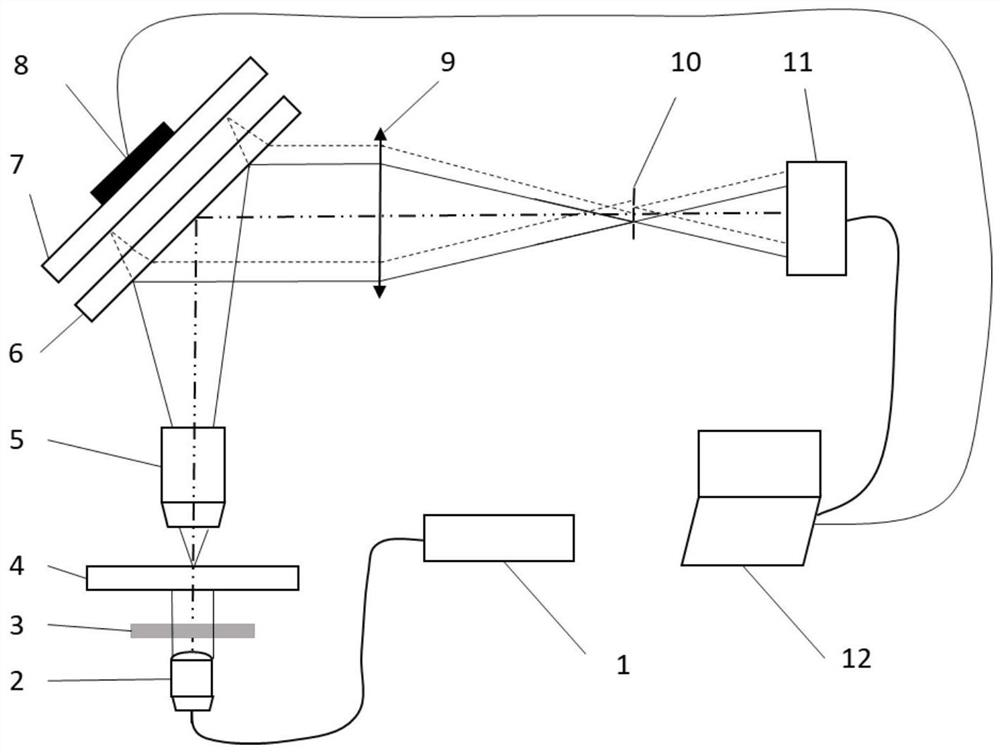
[0022] Such as figure 1 with image 3 As shown, this embodiment provides a common optical path phase-shift digital holographic microscopic measurement device, including a fiber laser 1, a fiber collimator 2, an adjustable attenuator 3, a sample to be tested 4, a microscopic objective lens 5, and a flat flat crystal I 6, plane flat crystal II7, piezoelectric ceramic driver 8, converging lens 9, filter 10, imaging detection device 11 and computer 12. This structure forms a transmission type common light path phase shift digital holographic microscopic measurement device.

[0023] The fiber laser 1 and the fiber collimator 2 are connected with a single-mode fiber to form a parallel beam;

[0024] The parallel beam passes through the adjustable attenuator 3 and directly irradiates the sample 4 to be tested, wherein the adjustable attenuator 3 can adjust the energy of the parallel beam so that the laser energy meets the requirements of the imaging detection device 11;

[0025] T...

Embodiment 2

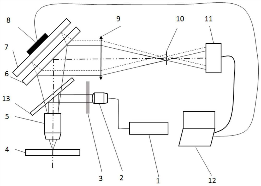
[0037] Such as figure 2 with image 3 As shown, on the basis of Embodiment 1, a beam splitter 13 is also arranged between the adjustable attenuator 3 and the microscope objective lens 5 to form a reflective common optical path phase-shift digital holographic microscopic measurement device, wherein the optical fiber The laser 1 and the fiber collimator 2 are connected with a single-mode fiber to form a parallel beam;

[0038] After the parallel beam passes through the adjustable attenuator 3, the beam is reflected by the beam splitter 13 and irradiates the microscopic objective lens 5, wherein the adjustable attenuator 3 can adjust the energy of the parallel beam so that the laser energy meets the imaging detection device 11 requirements;

[0039] The tested sample 4 is located on the focal plane of the microscope objective lens 5, so that the tested sample 4 can be clearly imaged on the imaging detection device 11;

[0040] Planar flat crystal I 6 and flat flat crystal II ...


PUM


Abstract

The invention discloses a common optical path phase-shift digital holographic microscopic measurement device, which comprises a fiber laser (1), a fiber collimator (2), an adjustable attenuator (3), and a microscopic objective lens arranged fixedly in sequence along the optical path direction (5), plane flat crystal I (6), plane flat crystal II (7), piezoelectric ceramic driver (8), converging lens (9), filter (10) and imaging detection device (11), the imaging The detector (11) is connected with the computer (12) through a cable. The invention utilizes two adjacent flat crystals to realize the phase difference change between the reference light and the test light, and obtain the phase-shift digital holographic microscopic imaging of the measured target. The device not only eliminates the influence of system noise in the non-common optical path, but also is easy to realize high-precision phase-shift holography, and effectively improves the phase reconstruction precision of digital holography.

Description

technical field [0001] The invention belongs to the technical field of digital holography, and in particular relates to a common optical path phase-shift digital holographic microscopic measurement device. Background technique [0002] Digital holography technology uses imaging detection devices to record interference information, and obtains the amplitude and phase information of the target through diffraction reconstruction, so as to realize the three-dimensional imaging of the measured target. It has the advantages of non-damaging, non-scanning, and quantitative analysis, and can be applied to imaging and measurement in the fields of micro-opto-electromechanical systems, particle analysis, and biological cells. [0003] In most cases, the digital holographic microscopic measurement device uses the Mach-Zehnder type or Tieman Green type interference optical path to realize the encounter interference between the test light modulated by the measured object and the reference ...

Claims


Application Information

Patent Timeline
Patent Type & Authority Patents(China)
IPC IPC(8): G03H1/04G03H1/12G01B11/24G01B9/021
CPCG03H1/0443G03H1/12G01B11/2441G01B9/02047G03H2001/0038G03H2001/005G03H2001/0445
Inventor 刘丙才冯方田爱玲刘卫国王红军朱学亮岳鑫潘永强
Owner XIAN TECH UNIV
Learn More