
A water conservancy project based on low latitude flow to high latitude river section anti-ice flood device

A water conservancy project, low-latitude technology, applied in water conservancy projects, water conservancy engineering equipment, buildings, etc., to achieve the effect of novel structure, reduced friction, and good antifreeze effect

Active Publication Date: 2022-01-28
张新贵
View PDF4 Cites 0 Cited by
  • Summary
  • Abstract
  • Description
  • Claims
  • Application Information

AI Technical Summary

Problems solved by technology

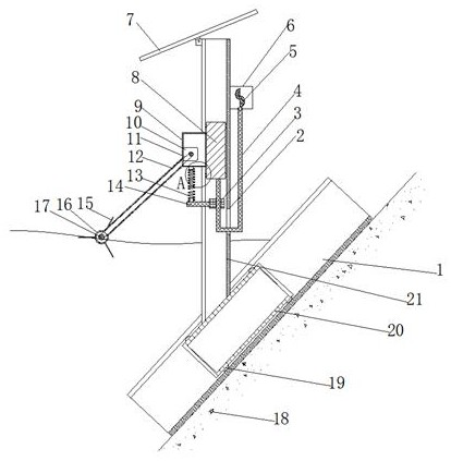
[0004] Based on the fact that the existing devices cannot solve the technical problem of icing at the edge of the overly long embankment, the present invention proposes a water conservancy project based on a low-latitude river section flowing to a high-latitude anti-flooding device

Method used


Image

  • A water conservancy project based on low latitude flow to high latitude river section anti-ice flood device
  • A water conservancy project based on low latitude flow to high latitude river section anti-ice flood device
  • A water conservancy project based on low latitude flow to high latitude river section anti-ice flood device

Examples


Embodiment 1

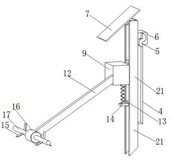
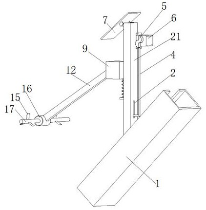
[0030] refer to Figure 1-5 , a water conservancy project based on low-latitude flow to high-latitude river section anti-flooding device, including a slope slide rail 1 fixed on the embankment 18, the chute of the slope slide rail 1 is slidably connected with a buoyancy tank 20 with a cavity inside, and The upper surface of the buoyancy tank 20 is fixed with a vertical C-shaped steel column 21, which is characterized in that a slide block 8 is slidably connected to the chute of the C-shaped steel column 21, and the side of the slide block 8 away from the bottom of the groove is fixed with a drive box 9 , the bottom end of the slider 8 is fixed with a U-shaped ejector rod 4, the back of the C-shaped steel column 21 is provided with a bar-shaped hole 2 matching the diameter of the U-shaped ejector rod 4, and the two sides of the C-shaped steel column 21 are fixed with The guide plate 3 that is adapted to the short bar in the U-shaped push rod 4, the side of the guide plate 3 awa...

Embodiment 2

[0041] refer to Figure 1-3 , a water conservancy project is based on low-latitude flow to high-latitude river section anti-flooding device, this embodiment compared with embodiment 1, also includes the top of the C-shaped steel column 21 is hinged with a solar panel 7, and the driving box 9 is provided with a A power storage device compatible with the solar panel 7.

[0042] Working principle: It can provide electric energy for the emergency power-off equipment of the electrical appliances in the equipment, avoiding that the temperature is too low, and the device in contact with the water surface will be frozen. At this time, the device is still running and the motor is burned, which plays a protective role in the device.


PUM


Abstract

The invention belongs to the technical field of water conservancy engineering, in particular to a water conservancy project based on a low-latitude flow-to-high-latitude river section ice flood prevention device. Aiming at the problem that the existing device cannot solve the problem of freezing at the edge of an overly long embankment, the following scheme is now proposed, including The slope slide rail fixed on the embankment, the chute of the slope slide rail is slidably connected with a buoyancy box with a cavity inside, and the upper surface of the buoyancy box is fixed with a vertical C-shaped steel column, and the C-shaped steel column A slider is slidably connected in the chute, and a drive box is fixed on the side of the slider far away from the bottom of the groove. A U-shaped ejector rod is fixed on the bottom end of the slider. A matching strip hole, a guide plate matching the short rod in the U-shaped ejector rod is fixed between the two sides of the C-shaped steel column, and a supporting plate is fixed on the side of the guide plate away from the bottom of the groove . The invention has novel structure and low cost, and a group of devices can act on a very long bank, and has good antifreeze effect.

Description

technical field [0001] The invention relates to the technical field of water conservancy engineering, in particular to an ice-flood prevention device for a water conservancy project based on the flow from low latitude to high latitude river section. Background technique [0002] When the ice flood season comes, the frozen river begins to melt, and due to latitude and other climate reasons, when the upstream river begins to melt, the downstream is still frozen. At this time, the frozen downstream will form an ice dam to block the river, causing The water flowing down from the upper reaches and the ice blocks washed away the river banks and caused disasters. The higher the latitude of the river, the higher the probability of severe ice floods. According to statistics, for rivers located in Russia north of 50°N, where the drainage area is larger than 100,000 km, the probability of severe ice flooding is 80%. [0003] In my country, for example, the Yellow River has a large no...

Claims


Application Information

Patent Timeline
Patent Type & Authority Patents(China)
IPC IPC(8): E02B1/00
CPCE02B1/00E02B1/003
Inventor 张新贵祖龙刘光东
Owner 张新贵
Learn More