


Quick Research
Generate reliable direction feasibility study reports for your R&D in just a few steps.

Technical Q&A
Discover and master advanced knowledge NOW. Basics, ideas, possibilities, all at once.

Find Solutions
As an expert in R&D theories, this can generate solutions to your technical problems instantly.

Evaluate Feasibility
Analyze your overall solution with one click, know your potential R&D risks in advance.

Monitor Landscape
Get weekly tech updates, stay abreast of the latest tech innovations and key insights.
Induction heating method of metal strip and induction heating equipment
一种感应加热设备、感应加热的技术,应用在感应加热、感应加热控制、感应加热装置等方向,能够解决加热效率低、难均匀加热等问题
- Summary
- Abstract
- Description
- Claims
- Application Information
AI Technical Summary
Problems solved by technology
Method used
Image


Examples
no. 1 Embodiment approach
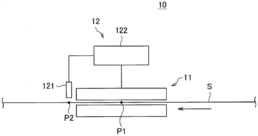
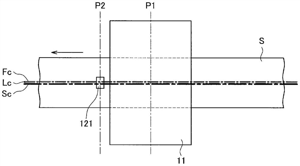
[0064] figure 1 It is a figure which shows the schematic structure of the induction heating apparatus 10 which concerns on 1st Embodiment of this invention by a side view. like figure 1 As shown, the induction heating device 10 includes an induction heating device 11 and a control device 12 . The induction heating device 11 is an induction heating device of the TF system for heating the continuously conveyed steel strip S, and is arranged at the position P1 on the conveying line of the steel strip S. As shown in FIG. In addition, the steel strip S is an example of the metal strip in this embodiment. The control device 12 includes a temperature scanner 121 as an example of a sensor, and an arithmetic device 122 . The temperature scanner 121 is arranged at a position different from the position P1 in the conveying direction, that is, a position P2 on the conveying line of the steel belt S. In the following description, in the conveyance line of the steel strip S, the upstrea...
no. 2 Embodiment approach
[0112] Figure 9 It is a figure which shows the example of arrangement|positioning of the induction heating apparatus provided with the divided magnetic core 212 in the induction heating facility of the 2nd Embodiment of this invention, and a temperature scanner. In addition, except Figure 9 Other than the configuration of the induction heating device 21 shown, the configuration and reference of the present embodiment figure 1 Since it is the same as the above-mentioned 1st Embodiment demonstrated etc., the repeated description is abbreviate|omitted. In addition, in the induction heating process of this embodiment, the control of the movement based on the estimated displacement amount ( Image 6 in step S13, Figure 7B In addition to the point that the object of step S112) is the magnetic core 212, and Image 6 , Figure 7A and Figure 7B Since the first embodiment shown is the same, the description is omitted.
[0113] like Figure 9 As shown, the induction heating d...
no. 3 Embodiment approach
[0116] Figure 10 It is a figure which shows the schematic structure of the induction heating installation concerning 3rd Embodiment of this invention. In addition, about the Figure 10 Elements denoted by the same reference numerals as those of the first embodiment in the configuration of the illustrated induction heating device 30 and steps denoted by the same reference numerals as those of the first embodiment in the flowcharts described later are the same as those of the first embodiment described above. Since the first embodiment is the same, the overlapping description is omitted.
[0117] like Figure 10 As shown, the induction heating device 30 includes an induction heating device 11 , a control device 32 and a steering mechanism 33 . The control device 32 includes a temperature scanner 121 and an arithmetic device 322 . The steering mechanism 33 includes a steering roller 331 arranged at a position P3 on the conveying line of the steel strip S, and an actuator 332...
PUM
 Abstract
Description
Claims
Application Information
 - R&D Engineer
- R&D Manager
- IP Professional
- Industry Leading Data Capabilities
- Powerful AI technology
- Patent DNA Extraction
Browse by: Latest US Patents, China's latest patents, Technical Efficacy Thesaurus, Application Domain, Technology Topic, Popular Technical Reports.
© 2024 PatSnap. All rights reserved.Legal|Privacy policy|Modern Slavery Act Transparency Statement|Sitemap|About US| Contact US: help@patsnap.com