A variable stiffness damping device with embedded coupling beams and its working method

A shock-absorbing device and variable-stiffness technology, which is used in earthquake-proof, wall, building types, etc., can solve the problem that the bearing capacity, reliability, and stiffness of coupling beam energy-dissipating devices are relatively strict and cannot fully meet the energy dissipation of high-rise structures. Shock absorption, complex stress state and other problems, to achieve the effect of improving seismic performance, reducing ultimate stress and strain, and improving fatigue performance

Active Publication Date: 2021-07-13
SOUTHEAST UNIV
View PDF0 Cites 0 Cited by
  • Summary
  • Abstract
  • Description
  • Claims
  • Application Information

AI Technical Summary

Problems solved by technology

[0004] However, the space of the coupling beam is small and the stress state is complex, so there are relatively strict requirements on the bearing capacity, reliability, and adjustable range of stiffness of the energy dissipation device of the coupling beam.
However, the existing devices may require external energy and complex control devices, or it is difficult to avoid plastic damage caused by yield energy consumption, and repair and replacement are rarely required after earthquakes, which cannot fully meet the needs of high-rise structures for energy dissipation and shock absorption.

Method used


Image

  • A variable stiffness damping device with embedded coupling beams and its working method
  • A variable stiffness damping device with embedded coupling beams and its working method
  • A variable stiffness damping device with embedded coupling beams and its working method

Examples


Embodiment Construction

[0043] In order to facilitate the understanding of the structure of the present invention, the following description will be made in conjunction with the accompanying drawings and embodiments.

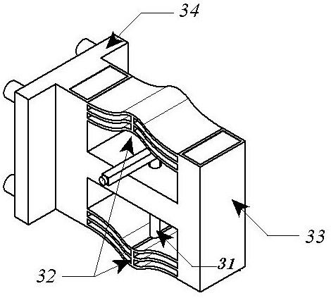
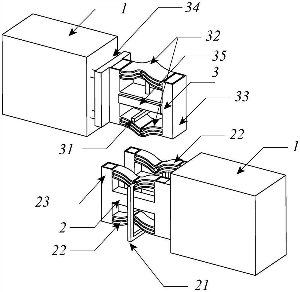
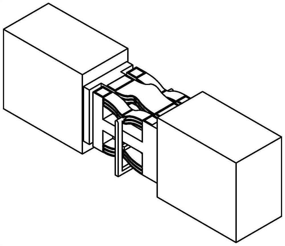
[0044] Such as figure 1 As shown, the device consists of a U-shaped joint 2 and a T-shaped joint 3 that match each other;

[0045] The closed side of the U-shaped joint 2 is connected to the connecting beam, and the open side is connected to the T-shaped joint 3. The U-shaped joint 2 includes a first steel member 23 with an H-shaped longitudinal section, and is connected to the upper and lower parts of the first steel member 23. The two concave hyperbolic spring steel sheet groups 22 on both sides are respectively the first concave hyperbolic spring steel sheet group and the second concave hyperbolic spring steel sheet group, and each group of concave hyperbolic spring steel sheet groups is composed of It is composed of a plurality of concave hyperbolic spring steel sheets, and a firs...


PUM


Abstract

The invention discloses a variable stiffness damping device embedded with connecting beams and a working method thereof. The device consists of U-shaped and T-shaped joints, hyperbolic spring steel sheets located at the upper and lower ends of the joints, and internal and external connecting members connecting the two joints; among them, the U-shaped and T-shaped joints are respectively connected to the truncated connecting beams on both sides, and the slot holes of the U-shaped joints It cooperates with the protrusion of the T-shaped joint, and its displacement is limited by the hyperbolic spring steel sheets at the upper and lower ends of the joint and the internal and external connecting members. The device can passively and accurately adjust the stiffness and damping characteristics of the coupling beam, optimize and control the dynamic response of high-rise structures for different environmental excitations such as earthquakes and wind vibrations, and does not require plastic deformation and external energy, and has a high application prospect.

Description

technical field [0001] The invention mainly relates to the field of structural vibration control, in particular to a variable stiffness damping device embedded with connecting beams and a corresponding working method. Background technique [0002] The beam-shear wall structure is the most massive and wide-ranging structural form of multi-story structures in my country. It has high lateral stiffness and strength, but poor deformation capacity, and the effect of dampers based on interstory displacement energy dissipation and shock absorption is limited. Scholars have found that an effective way to control its dynamic response is to apply energy dissipation coupling beams. In order to take into account the differential environmental excitation of the structure under wind vibration and earthquake action of different regression periods, it is required that the energy-dissipating coupling beams have significantly different stiffness and damping characteristics under different work...

Claims


Application Information

Patent Timeline
Patent Type & Authority Patents(China)
IPC IPC(8): E04B1/98E04H9/02E04B2/56
CPCE04B1/98E04B2/56E04H9/02E04H9/021
Inventor 张中文徐赵东
Owner SOUTHEAST UNIV
Why Eureka
Try Eureka