
Deodorizing shoe cabinet based on smart home

A smart home and shoe cabinet technology, applied to furniture accessories, cabinets with folding features, parts of pumping devices for elastic fluids, etc., can solve the problem of being difficult to store different types of shoes and the deodorization effect of traditional shoe cabinets Poor, fixed storage space and other issues, to achieve the effect of improving stability, improving anti-skid performance, and increasing contact range

Inactive Publication Date: 2020-10-16
胡立元
View PDF0 Cites 0 Cited by
  • Summary
  • Abstract
  • Description
  • Claims
  • Application Information

AI Technical Summary

Problems solved by technology

[0003] Most of the traditional shoe cabinets have a relatively simple structure. The structure of the shoe cabinet is generally fixed, and it is inconvenient to adjust. The storage space is also relatively fixed. Therefore, there are certain limitations

Method used


Image

  • Deodorizing shoe cabinet based on smart home
  • Deodorizing shoe cabinet based on smart home
  • Deodorizing shoe cabinet based on smart home

Examples


Embodiment 1

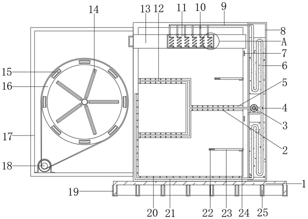
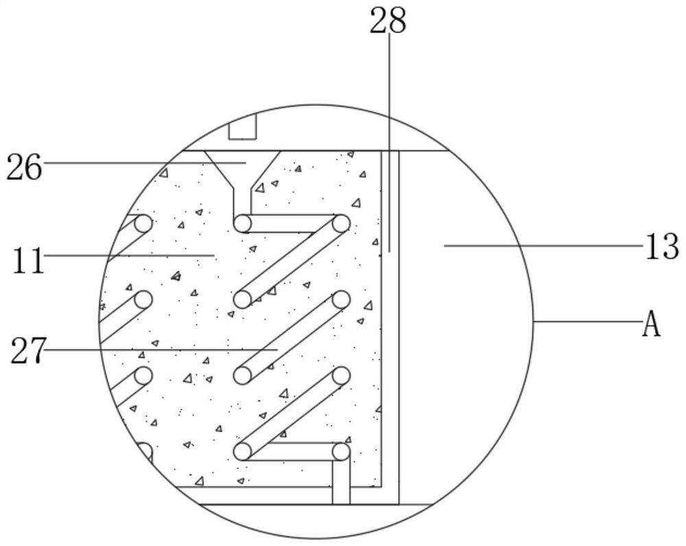
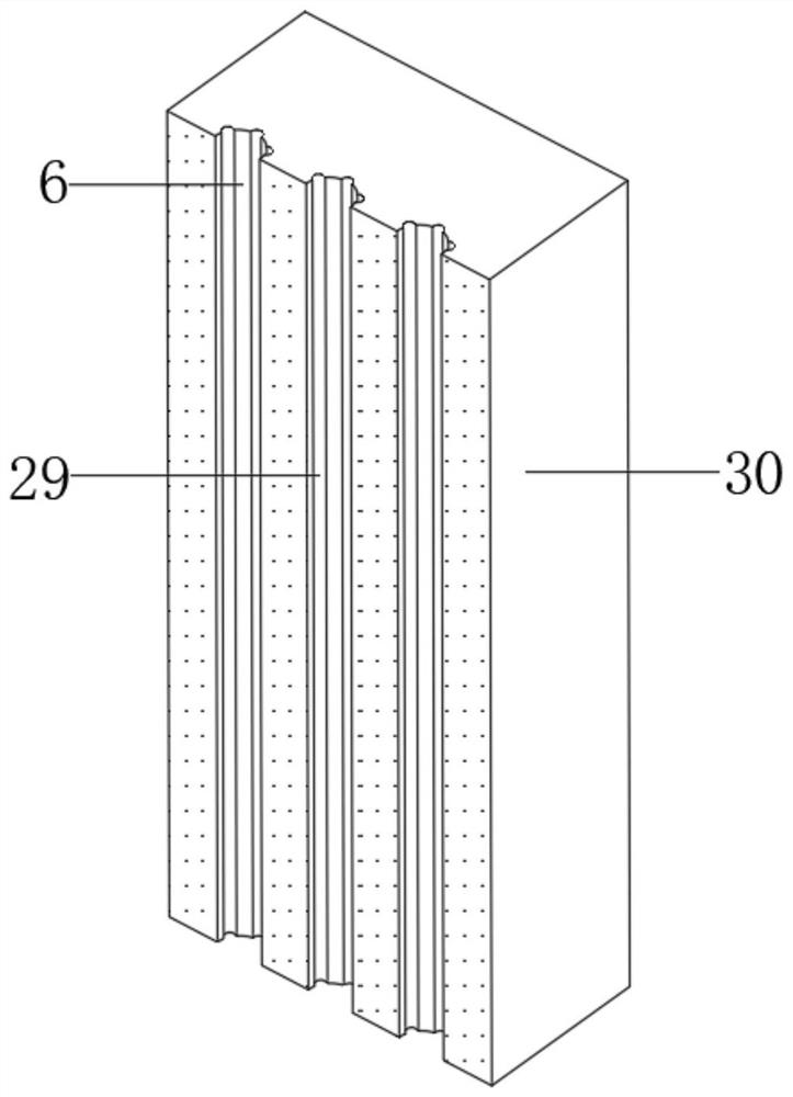
[0030] refer to Figure 1-4 , a deodorant shoe cabinet based on smart home, comprising a base 1, the top outer wall of the base 1 is fixed with a cabinet body by bolts, and one side of the cabinet body is fixed with an auxiliary cabinet 8 by bolts, and the inner wall of the cabinet body is fixed with bolts Y-shaped inverted frame 5, and Y-shaped inverted frame 5 is all provided with Y-shaped air duct 12, and both sides of Y-shaped air duct 12 are all provided with the bucket-shaped slotted hole 2 that communicates with the cabinet inner wall, one of auxiliary cabinet 8 The side inner wall is fixed with the exhaust fan 3 connected with the Y-shaped air duct 12 by bolts, and the output shaft of the exhaust fan 3 is fixedly connected with a T-shaped pipe, and the upper and lower ends of the auxiliary cabinet 8 are respectively fixedly equipped with activated carbon cylinders 30, and The inside of the activated carbon cylinder 30 is provided with a curved air duct 6 connected to t...

Embodiment 2

[0041] refer to Figure 5 , a deodorant shoe cabinet based on smart home. Compared with Embodiment 1, this embodiment also includes a spiral groove cavity 32 on the inner wall of the curved air duct 6, and a part of the curved air duct 6 close to the spiral groove cavity 32 Spiral tabs 33 are welded to the sides.

[0042] When the present invention is in use: use the spiral groove cavity 32 arranged on the curved air duct 6 to cooperate with the spiral fin 33 to guide the air, so that the air moves in the curved air duct 6 in a spiral path, thereby further improving the air and activated carbon cylinder 30 The degree of contact, in order to achieve the purpose of improving the deodorizing effect of the device.


PUM


Abstract

The invention belongs to the technical field of smart home and particularly relates to a deodorizing shoe cabinet based on smart home. The objective of the invention is to solve problems that most oftraditional shoe cabinets are simpler in structure, more fixed in design, difficult to be suitable for storage of different types of shoes and poor in deodorizing effects. According to the scheme, theshoe cabinet comprises a base, a cabinet body is fixed to the outer wall of the top of the base through bolts, an auxiliary cabinet is fixed to one side of the cabinet body through bolts, Y-shaped inverted frames are fixed to the inner wall of the cabinet body through bolts, Y-shaped air ducts are formed in the Y-shaped inverted frames, and bucket-shaped groove holes communicated with the inner wall of the cabinet body are formed in the two sides of each Y-shaped air duct. Air in the cabinet body can be uniformly blown to the curved air duct through the Y-shaped air ducts and the bucket-shaped slotted holes through splayed air division plates, the contact area of the air and the activated carbon cylinder is effectively increased by utilizing the strip-shaped branch ducts, and the movementpath of the air is prolonged by utilizing the curved air duct, so that the air is effectively adsorbed and deodorized.

Description

technical field [0001] The invention relates to the technical field of smart home, in particular to a smart home-based deodorizing shoe cabinet. Background technique [0002] Furniture refers to the category of utensils and facilities necessary for human beings to maintain normal life, engage in production practice and carry out social activities. Furniture also follows the footsteps of the times and continues to develop and innovate. Up to now, there are many categories, different materials, complete varieties, and different uses. It is an important foundation for building a working and living space. Furniture is composed of four factors: material, structure, appearance and function, among which function is the forerunner and the driving force to promote the development of furniture; structure is the backbone and the basis for realizing the function. These four factors are interrelated and restrict each other. Since furniture is designed and produced to meet people's cer...

Claims


Application Information

Patent Timeline
IPC IPC(8): A47B61/04A47B43/00A47B96/02A47B97/00A61L2/10A61L2/26F04D29/64B01D53/04
CPCA47B43/00A47B61/04A47B96/02A47B97/00A47B2220/0002A47B2220/0061A47B2220/0091A61L2/10A61L2/26B01D53/04B01D53/0407F04D29/64
Inventor 胡立元
Owner 胡立元
Learn More