TM mode dielectric filter

A dielectric filter and dielectric resonator technology, which is applied in the field of radio frequency communication, can solve problems affecting filter Q value and intermodulation, dielectric resonator contact, etc., achieve high intermodulation, high Q value, and ensure reliability.

Pending Publication Date: 2020-10-13
SHENZHEN GRENTECH RF COMM LTD
View PDF0 Cites 0 Cited by
  • Summary
  • Abstract
  • Description
  • Claims
  • Application Information

AI Technical Summary

Problems solved by technology

[0003] In the existing TM mode dielectric filter, the top and bottom surfaces of the dielectric resonator usually cannot achieve good contact with its cover plate and the bottom of its cavity, thus affecting the Q value and intermodulation of the filter

Method used


Image

  • TM mode dielectric filter
  • TM mode dielectric filter
  • TM mode dielectric filter

Examples


Embodiment Construction

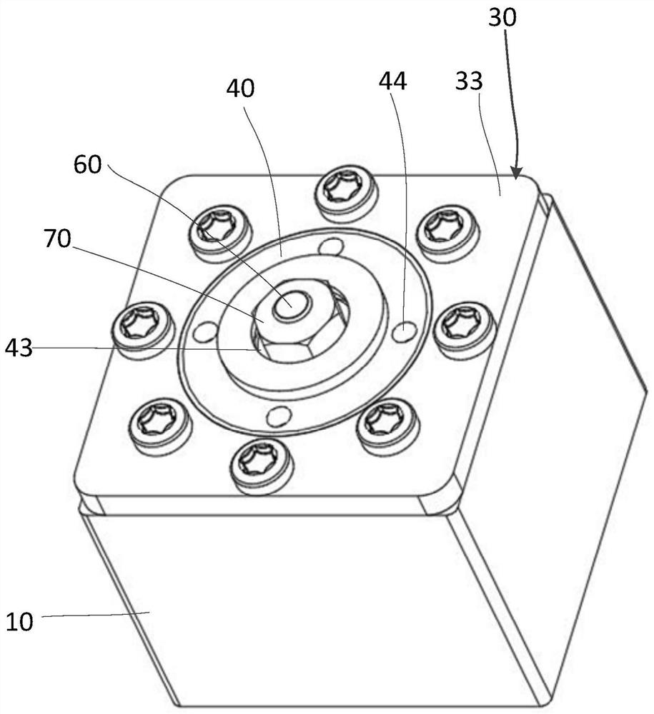
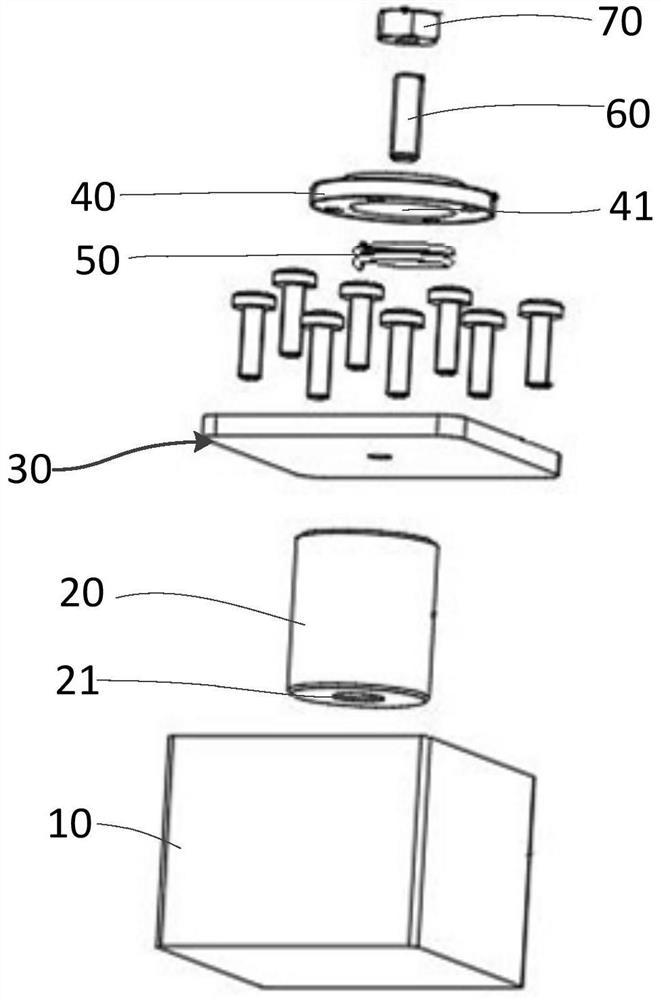
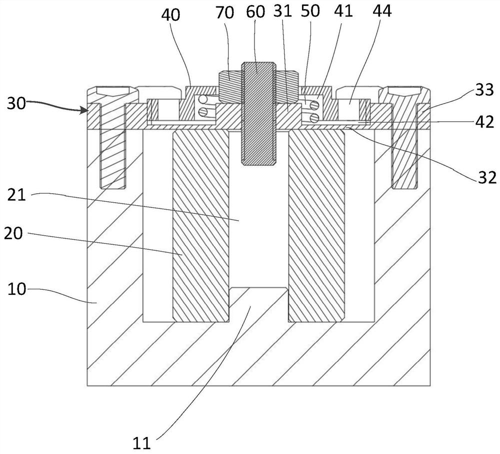
[0037] see Figure 1 to Figure 5 , the present embodiment provides a TM mode dielectric filter, including a cavity 10 with an open end, a dielectric resonator 20 located in the cavity 10 , a cover plate 30 and a pressure block 40 mounted on the open end of the cavity 10 .

[0038] The dielectric resonator 20 is a hollow structure with a cavity 21 extending along its axial direction.

[0039] The cover plate 30 includes a pressing portion 31 , a deforming portion 32 and a peripheral mounting portion 33 . The deformation part 32 and the pressing part 31 are used to contact the top surface of the dielectric resonator 20 . The peripheral mounting portion 33 surrounds the pressing portion 31 for mounting the cover plate 30 to the open end of the cavity 10 , and the peripheral mounting portion 33 mounts the cover plate 30 to the open end of the cavity 10 through fasteners such as screws. The deforming part 32 is connected between the pressing part 31 and the peripheral mounting pa...


PUM

PropertyMeasurementUnit
Thicknessaaaaaaaaaa

Abstract

The invention provides a TM mode dielectric filter. The filter comprises a cavity with an open end, a dielectric resonator located in the cavity and a cover plate installed at the open end of the cavity. The cover plate comprises a compression part, a deformation part and a peripheral mounting part; the deformation part and the compression part are in contact with a dielectric resonator; the peripheral mounting part surrounds the compression part and is used for installing the cover plate to the open end of the cavity; the deformation part is connected between the compression part and the peripheral mounting part; and the deformation part can deform to allow the compression part to approach to or move away from the bottom of the cavity. The TM mode dielectric filter further comprises a pressure applying block; the pressure applying block is installed on the compression part or the deformation part so as to apply pressure to the compression part or the deformation part. According to theTM mode dielectric filter of the invention, the high Q value, high intermodulation and other performances of the TM mode dielectric filter are ensured.

Description

【Technical field】 [0001] The invention relates to the field of radio frequency communication, in particular to a TM (transverse magnetic) mode dielectric filter. 【Background technique】 [0002] The TM mode dielectric filter is used as the transceiver filter of the key components of the radio frequency front end of the mobile base station. Its performance directly affects the quality of communication. With the development of mobile communication networks and the approach of 5G technology, the dielectric filter has a miniaturized and high Q value. It is widely used in 5G technology. [0003] In the existing TM mode dielectric filter, the top and bottom surfaces of the dielectric resonator usually cannot achieve good contact with the cover plate and the bottom of the cavity, thus affecting the Q value and intermodulation of the filter. 【Content of invention】 [0004] The main purpose of the present invention is to provide a TM mode dielectric filter, which ensures the high Q...

Claims


Application Information

Patent Timeline
IPC IPC(8): H01P1/20
CPCH01P1/2002
Inventor 张登高黄永红李贵强
Owner SHENZHEN GRENTECH RF COMM LTD
Why Eureka
Try Eureka