Cylindrical workpiece polishing machine

A circular workpiece and cylindrical technology is applied in the field of cylindrical workpiece polishing machines, which can solve the problems of increasing labor intensity of workers, high labor intensity, and inability to guarantee accuracy, etc., so as to reduce labor intensity of workers, increase polishing range, and improve polishing. The effect of efficiency

Pending Publication Date: 2020-10-13
NORTH CHINA UNIV OF WATER RESOURCES & ELECTRIC POWER
View PDF0 Cites 0 Cited by
  • Summary
  • Abstract
  • Description
  • Claims
  • Application Information

AI Technical Summary

Problems solved by technology

[0002] The polishing of cylindrical workpieces occupies a large proportion in the polishing field. At present, manual polishing or semi-automatic polishing is mostly used for cylindrical workpieces. Manual polishing is performed by hand-held polishing machines, or directly by holding polishing sandpaper by hand, which is labor-intensive. , the efficiency is not high, most of the semi-automatic polishing is to fix and rotate the cylindrical workpiece, then fix the polishing device to one side of the cylindrical workpiece, and polish the polishing belt in contact with the cylindrical surface, but when the cylindrical workpiece is polished, manual work is required Only by moving the workpiece left and right can the complete polishing of the cylindrical workpiece be realized, which increases the labor intensity of the workers, and manual movement cannot guarantee the accuracy, which affects the polishing quality of the workpiece; moreover, it is difficult to rotate the cylindrical workpiece when manually operating the cylindrical workpiece , so the polishing belt is troublesome to polish the entire side of the cylindrical workpiece, and the efficiency is not high, and the relatively long cylindrical workpiece cannot be clamped and fixed on the polishing machine, which affects the working efficiency of the polishing equipment

Method used


Image

  • Cylindrical workpiece polishing machine
  • Cylindrical workpiece polishing machine
  • Cylindrical workpiece polishing machine

Examples


Embodiment 1

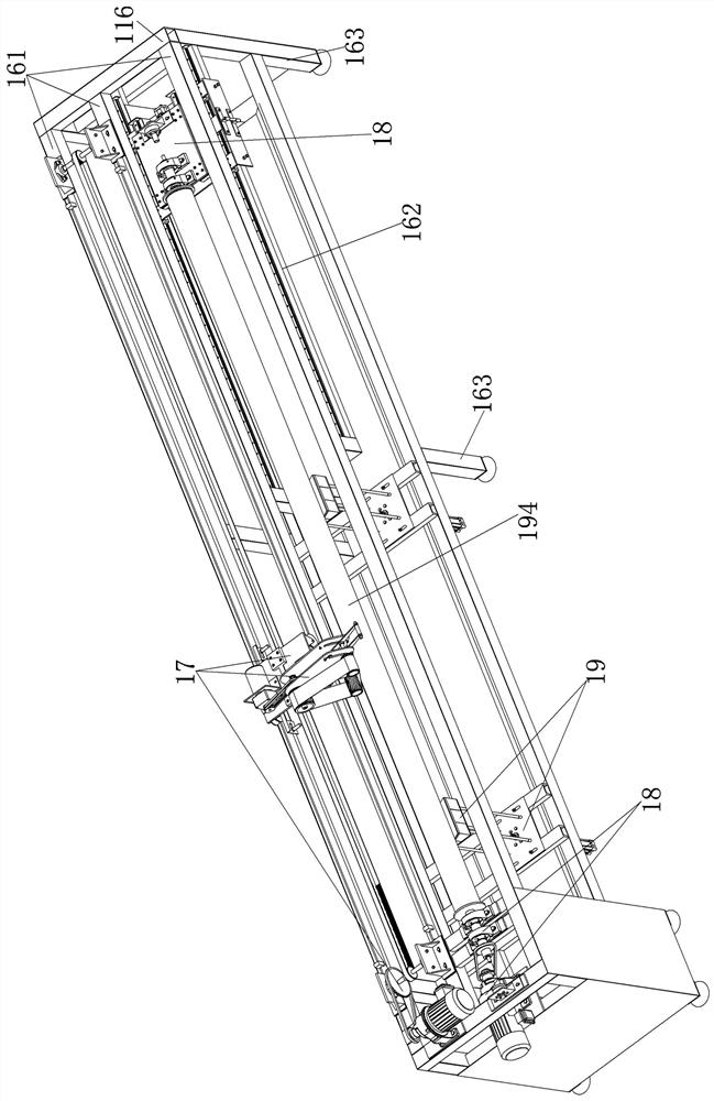
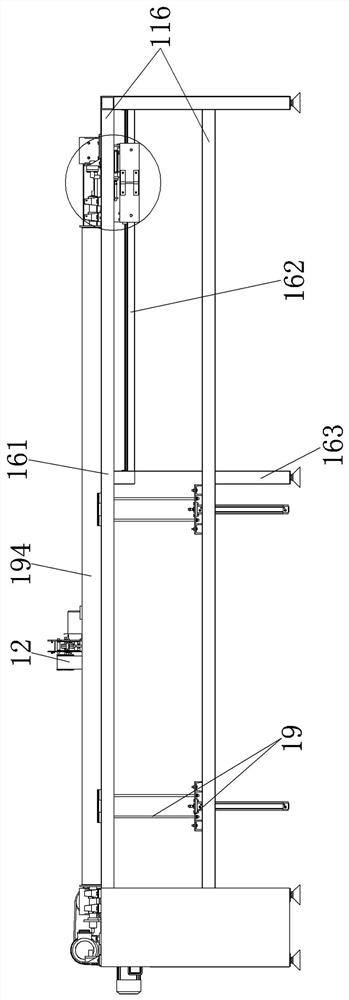
[0047] Embodiment 1, referring to the accompanying drawings (1-22) of the specification, a cylindrical workpiece polishing machine includes a bracket, a reciprocating polishing device, and a cylindrical workpiece driving device; the bracket is a cuboid bracket welded by several square steel pipes, The upper end of the bracket is connected by three upper beams, and the lower end of the two upper beams on the outer side is provided with two identical slide rail support beams, and the bracket is provided with several outriggers downward;

[0048] The reciprocating polishing device is installed on the inner side of the bracket. A reciprocating polishing device for circular workpieces includes a mobile platform, a polishing belt tensioning device, a track, and a reciprocating drive device. The track is two corners arranged side by side. Iron, the reciprocating driving device is located at both ends of the track, the reciprocating driving device includes a bearing seat, a driving bel...


PUM


Abstract

The invention relates to a cylindrical workpiece polishing machine which comprises a support, a reciprocating polishing device and a cylindrical workpiece driving device. The cylindrical workpiece driving device can drive a cylindrical workpiece installed on the polishing machine to rotate, and can adapt to cylindrical workpieces with different lengths. The reciprocating polishing device can drivea polishing belt tensioning device to move left and right to comprehensively polish the cylindrical workpiece, a push-pull arm locking device on the polishing belt tensioning device can lock a polishing belt at a working position, a sliding bar between a supporting block and a lower sliding rod on the polishing belt tensioning device can provide downward elastic force to press down the lower sliding rod when two push-pull arms slide a clamping plate upwards to be separated from a lower sliding shaft, therefore, a belt wheel at the lower position is driven to press down, and the phenomenon that a belt on the belt wheel is loosened and falls down when the two push-pull arms move upwards is avoided.

Description

technical field [0001] The invention relates to the technical field of cylinder polishing, in particular to a cylindrical workpiece polishing machine. Background technique [0002] The polishing of cylindrical workpieces occupies a large proportion in the polishing field. At present, manual polishing or semi-automatic polishing is mostly used for cylindrical workpieces. Manual polishing is performed by hand-held polishing machines, or directly by holding polishing sandpaper by hand, which is labor-intensive. , the efficiency is not high, most of the semi-automatic polishing is to fix and rotate the cylindrical workpiece, then fix the polishing device to one side of the cylindrical workpiece, and polish the polishing belt in contact with the cylindrical surface, but when the cylindrical workpiece is polished, manual work is required Only by moving the workpiece left and right can the complete polishing of the cylindrical workpiece be realized, which increases the labor intens...

Claims


Application Information

Patent Timeline
Patent Type & Authority Applications(China)
IPC IPC(8): B24B21/02B24B21/18B24B21/20B24B21/22B24B41/06B24B47/12B24B47/22
CPCB24B21/02B24B21/18B24B21/20B24B21/22B24B41/062B24B47/12B24B47/22
Inventor 张庆华
Owner NORTH CHINA UNIV OF WATER RESOURCES & ELECTRIC POWER
Why Eureka
Try Eureka