Specially-made air cylinder swing mechanism

A swing mechanism and cylinder technology, applied in the direction of manufacturing tools, grinding drive devices, surface polishing machine tools, etc., can solve the problems of large belt wear, insufficient structure, poor polishing effect, etc.

Pending Publication Date: 2022-06-03
江门市亚泰智能抛磨科技有限公司
View PDF0 Cites 0 Cited by
  • Summary
  • Abstract
  • Description
  • Claims
  • Application Information

AI Technical Summary

Problems solved by technology

Since some workpieces have many curved surfaces on the surface, the processing is more complicated, and the polishing wheel needs to swing to a certain extent, but the existing swing structure generally uses an eccentric wheel structure, and the eccentric wheel is used to push the polishing wheel to swing, but this structure The polishing wheel is not fine enough, and the polishing effect is not good. The other is to use the activity margin between the belt and the rotating shaft to control the polishing wheel to swing, but this structure wears a lot on the belt, and at the same time, most of the transmission devices of this type of swing structure Just use a simple dust cover, the dust generated by polishing is easy to enter the transmission system, affecting the life of the machine

Method used


Image

  • Specially-made air cylinder swing mechanism
  • Specially-made air cylinder swing mechanism
  • Specially-made air cylinder swing mechanism

Examples


Embodiment Construction

[0024] The following describes in detail the embodiments of the present invention, examples of which are illustrated in the accompanying drawings, wherein the same or similar reference numerals refer to the same or similar elements or elements having the same or similar functions throughout. The embodiments described below with reference to the accompanying drawings are exemplary, only used to explain the present invention, and should not be construed as a limitation of the present invention.

[0025] In the description of the present invention, it should be understood that the azimuth description, such as the azimuth or position relationship indicated by up, down, front, rear, left, right, etc., is based on the azimuth or position relationship shown in the drawings, only In order to facilitate the description of the present invention and simplify the description, it is not indicated or implied that the indicated device or element must have a particular orientation, be construc...


PUM


Abstract

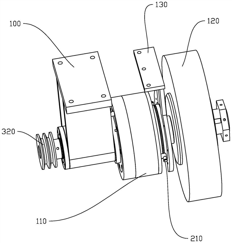
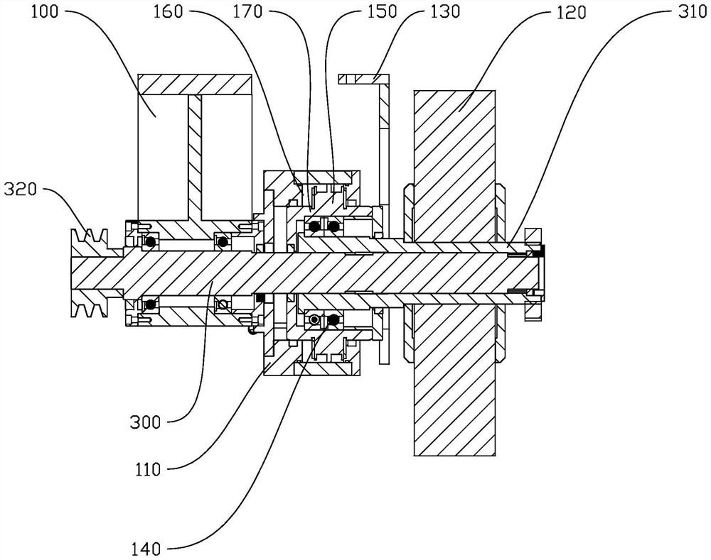
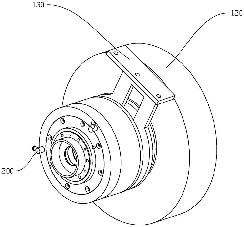
The invention discloses a special air cylinder swing mechanism which is applied to a polishing machine and discloses a cylinder barrel which is provided with a hollow channel, a guide groove is further formed in the cylinder barrel, and a first air inlet and a second air inlet are formed in the two sides of the cylinder barrel. The piston block is mounted in the guide groove, abuts against the inner wall of the guide groove and communicates with the first air inlet and the second air inlet; the mounting ring is movably mounted on the hollow channel, and the mounting ring is connected with the piston block; the rotating shaft is arranged in the hollow channel and is of an inner-outer double-layer main shaft structure, one end of an inner main shaft is connected with a transmission mechanism to complete rotating motion, the other end of the inner main shaft is connected with an outer main shaft, and a spline shaft and a spline groove, matched with each other, of the inner main shaft and the outer main shaft transmit rotating power. The rotating shaft is arranged in the cylinder, so that the rotating shaft can be protected, and the service life of the rotating shaft is prolonged; and the polishing wheel can swing by a certain angle when completing rotating motion, so that the polishing range of the polishing machine is enlarged, and the working efficiency of the polishing machine is improved.

Description

technical field [0001] The invention relates to the technical field of polishing equipment, in particular to a special cylinder swing mechanism. Background technique [0002] At present, with the progress and development of society and the improvement of people's living standards, the requirements for daily necessities are getting higher and higher, especially for the appearance of metal and other products, which must have both visual effects and good feel effects. , so it brings broad market prospects to the surface treatment of metal and other products. The existing polishing machines on the market mainly rotate the grinding head, or the workpiece rotates, so as to process the surface of the workpiece. Because the surface of some workpieces is more cambered, the processing is more complicated, and the polishing wheel needs to swing to a certain extent, but the existing swing structure generally uses an eccentric wheel structure, which uses an eccentric wheel to push the p...

Claims


Application Information

Patent Timeline
IPC IPC(8): B24B41/04B24B47/12B24B47/00B24B29/02
CPCB24B41/04B24B47/12B24B47/00B24B29/02
Inventor 郑小军郑建勇郑建军郑名逸
Owner 江门市亚泰智能抛磨科技有限公司
Why Eureka
Try Eureka