Medium-frequency induction heating furnace body, furnace body manufacturing method and temperature control method

An induction heating furnace and manufacturing method technology, applied in the furnace body manufacturing method and temperature control, in the field of medium-frequency induction heating furnace body, can solve the problems of scale formation, low temperature signal of the thermometer, and contact with air, etc., to achieve Simplify the manufacturing process, ensure the pass rate, and ensure the effect of not overheating

Pending Publication Date: 2020-10-13
HANGZHOU KEYUAN ELECTRIC FURNACE CO LTD
View PDF0 Cites 0 Cited by
  • Summary
  • Abstract
  • Description
  • Claims
  • Application Information

AI Technical Summary

Problems solved by technology

[0003] The furnace body of the existing intermediate frequency induction heating furnace generally has a furnace lining inside, and a forehearth through which the billet passes is formed in the middle of the furnace lining; the furnace lining of the furnace body of the existing intermediate frequency induction heating furnace is a seamless whole. When measuring the temperature of the billet, a thermometer can only be installed at the outlet of the furnace lining material channel to detect the temperature of the billet. The defect caused by this method of temperature measurement at the outlet is that the billet will meet In contact with air, the end surface of the billet will cool down or form oxide scales, which will cause the temperature signal fed back to the thermometer to be low

Method used


Image

  • Medium-frequency induction heating furnace body, furnace body manufacturing method and temperature control method
  • Medium-frequency induction heating furnace body, furnace body manufacturing method and temperature control method
  • Medium-frequency induction heating furnace body, furnace body manufacturing method and temperature control method

Examples


Embodiment 1

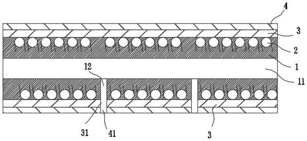
[0048] refer to figure 2 As shown, this embodiment provides a medium frequency induction heating furnace body, including a furnace shell 4 and a furnace lining 1, and a forehearth 11 is provided in the middle of the furnace lining 1 for the blank to pass through. During forging, the blank passes along the forehearth 11 Axial travel.

[0049] The furnace lining 1 is provided with an induction coil 2 that extends axially along the forehearth 11 and is spirally wound outside the forehearth 11 ; wherein the induction coil 2 is wound by a copper tube.

[0050] The side wall of the furnace lining 1 is spaced apart from a number of temperature measuring holes 12 distributed along the axial direction of the furnace lining 1, wherein the temperature measuring holes 12 are arranged radially along the furnace lining 1 and communicate with the material channel 11 through the side wall of the furnace lining 1. The temperature hole 12 is located at the interval between two adjacent turns ...

Embodiment 2

[0062] Such as Figure 2-Figure 4 As shown, the present embodiment provides a method for manufacturing the intermediate frequency induction heating furnace described in Embodiment 1, which specifically includes the following steps:

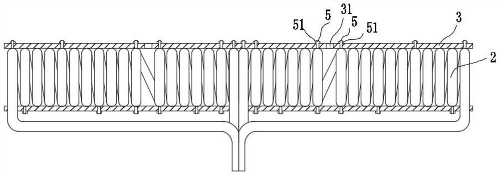
[0063] S100. Winding the induction coil 2: place the copper tube on the copper tube winding machine, wind the copper tube in a spiral shape through the copper tube winding machine to form a section of induction coil 2; repeat this step, and wind several sections according to actual needs Induction coil 2.

[0064] Finally, all the induction coils 2 are connected and formed in series or in parallel, and it should be noted that the induction coils 2 are arranged coaxially.

[0065] In this step, according to the position of the temperature measuring hole 12 that needs to be opened, the gap between the two turns of the induction coil 2 corresponding to the positions on both sides of the temperature measuring hole 12 is appropriately increased, so as...

Embodiment 3

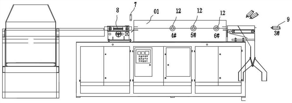
[0086] combine figure 1 As shown, this embodiment provides a temperature control method applied to the electric furnace body 01 in Embodiment 1, which specifically includes the following steps:

[0087] In the first step, the temperature measuring instrument 9 coaxially arranged with the temperature measuring hole 12 is correspondingly installed outside each of the temperature measuring holes 12 (the temperature measuring instrument at the temperature measuring hole is not shown), wherein the temperature measuring instrument 9 is specifically Infrared thermometers can be used.

[0088] All the thermometers 9 are connected with the control device, and the control device is used to control and adjust the input power of the induction coil 2 according to the temperature signal fed back by the thermometer 9 . The control device can be a PLC or a finished instrument, and of course it can also be other control devices, which are not specifically limited here; the following uses PLC ...


PUM


Abstract

The invention relates to the technical field of medium-frequency induction heating furnaces, in particular to a medium-frequency induction heating furnace body, a furnace body manufacturing method anda temperature control method. The medium-frequency induction heating furnace body comprises a furnace lining, a material channel allowing a blank to pass through is formed in the middle of the furnace lining, and an induction coil which extends in axial direction of the material channel and is spirally wound on outer side of the material channel is arranged in the furnace lining; and a pluralityof temperature measuring holes are formed in the side wall of the furnace lining in the axial direction of the furnace lining at intervals, the temperature measuring holes are formed in the radial direction of the furnace lining and penetrate through the side wall of the furnace lining, and the temperature measuring holes are located at the intervals between every two adjacent turns of coils of the induction coil. The invention further provides a manufacturing method of the medium-frequency induction heating furnace body and a temperature control method of the medium-frequency induction heating furnace. According to the furnace body, the temperature measuring holes are formed in the side wall of the furnace body for temperature measurement instead of adopting the temperature measurement mode at a discharge port so that the temperature measurement accuracy can be improved.

Description

technical field [0001] The present invention relates to the technical field of intermediate frequency induction heating furnaces, in particular, to an intermediate frequency induction heating furnace body, a furnace body manufacturing method and a temperature control method. Background technique [0002] The intermediate frequency induction heating furnace is widely used in the forging industry due to its superior performance. It mainly uses the intermediate frequency magnetic field established by the intermediate frequency power supply to generate induction eddy current inside the metal blank and generate heat to achieve the purpose of heating the metal blank. [0003] The furnace body of the existing intermediate frequency induction heating furnace generally has a furnace lining inside, and a forehearth through which the billet passes is formed in the middle of the furnace lining; the furnace lining of the existing intermediate frequency induction heating furnace body is a ...

Claims


Application Information

Patent Timeline
IPC IPC(8): B21J17/02F27B9/06F27B9/20F27B9/40F27B9/36F27B9/32F27D1/16
CPCB21J17/02F27B9/067F27B9/20F27B9/32F27B9/36F27B9/40F27D1/1626
Inventor 许金平
Owner HANGZHOU KEYUAN ELECTRIC FURNACE CO LTD
Why Eureka
Try Eureka