A guide fixture for pedicle screw placement
A technology of pedicle screws and fixtures, applied in medical science, surgery, fixers, etc.
- Summary
- Abstract
- Description
- Claims
- Application Information
AI Technical Summary
Problems solved by technology
Method used
Image
Examples
Embodiment 1
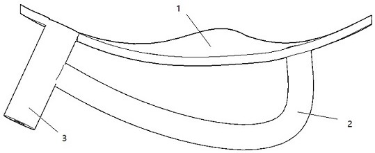
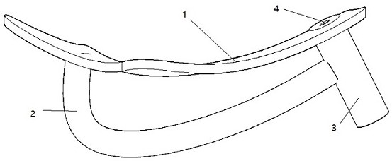
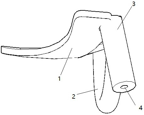
[0033] Example 1, such as Figure 1-6 The shown guide fixture for pedicle 3D printing screw placement is composed of a bonding sheet 1, a guide cylinder 3 and an arc-shaped handle 2. The arc-shaped handle 2 is placed on the back of the bonding sheet 1. One end of the arc-shaped handle 2 is connected to One side of the bonding piece 1 is fixedly connected, and the other end is fixedly connected with the guide cylinder 3. The arc-shaped handle 2 is 39 mm long and 4.5 mm in diameter; The side of the bonding sheet 1 that is in contact with the back of the spine is provided with a curved surface that can be bonded to both sides of the back of the spine, with a thickness of 3mm; the guide tube 3 is a hollow short round tube with a length of 25mm and an inner diameter of 2.2mm, embedded in the other side In the bonding sheet 1, the center communicates with the bonding sheet to form a guide through hole 4, which is filled with a stretchable and expandable sealing rubber 7, and a rubbe...
Embodiment 2
[0034] Example 2, such as Figure 1-4 The pedicle 3D printing screw setting guide fixture shown is composed of a bonding sheet 1, a guide cylinder 3 and an arc-shaped handle 2. The arc-shaped handle 2 is placed on the back of the bonding sheet 1. One end of the arc-shaped handle 2 is connected to One side of the bonding piece 1 is fixedly connected, and the other end is fixedly connected with the guide cylinder 3. The arc-shaped handle 2 is 40mm long and 4.4mm in diameter; The side of the bonding sheet 1 that is in contact with the back of the spine is provided with a curved surface that can be bonded to both sides of the back of the spine, with a thickness of 2mm; the guide tube 3 is a hollow short round tube with a length of 20mm and an inner diameter of 2.1mm, embedded in the other side In the laminating sheet 1 , the center communicates with the laminating sheet 1 to form a guide through hole 4 , the guide through hole 4 is filled with a stretchable and expandable sealing ...
Embodiment 3
[0035] Example 3, such as Figure 1-4 The shown guide fixture for pedicle 3D printing screw placement is composed of a bonding sheet 1, a guide cylinder 3 and an arc-shaped handle 2. The arc-shaped handle 2 is placed on the back of the bonding sheet. The side bonding piece 1 is fixedly connected, and the other end is fixedly connected with the guide cylinder 3. The arc-shaped handle 2 is 39 mm long and 4.5 mm in diameter; The side of the joint piece 1 that is in contact with the back of the spine is provided with a curved surface that can be attached to both sides of the back of the spine, with a thickness of 5mm; the guide cylinder 3 is a hollow short round tube with a length of 30mm and an inner diameter of 2.1mm, which is embedded in the other side. In the bonding sheet 1, the center communicates with the bonding sheet 1 to form a guide through hole 4, which is filled with a stretchable and expandable sealing rubber 7, and a rubber baffle 8 is provided at the bottom.
PUM
 Abstract
Description
Claims
Application Information
 - R&D
- Intellectual Property
- Life Sciences
- Materials
- Tech Scout
- Unparalleled Data Quality
- Higher Quality Content
- 60% Fewer Hallucinations
Browse by: Latest US Patents, China's latest patents, Technical Efficacy Thesaurus, Application Domain, Technology Topic, Popular Technical Reports.
© 2025 PatSnap. All rights reserved.Legal|Privacy policy|Modern Slavery Act Transparency Statement|Sitemap|About US| Contact US: help@patsnap.com


