
Topological structure of auxiliary converter for locomotive

A technology of auxiliary converter and topology structure, which is applied in the direction of machines/engines, control electromechanical brakes, mechanical equipment, etc., can solve the problems of low motor efficiency and power factor, low efficiency of asynchronous motors, etc., to improve efficiency, improve efficiency and Effects of power factor and reliability improvement

Active Publication Date: 2020-10-09
CRRC YONGJI ELECTRIC CO LTD
View PDF18 Cites 0 Cited by
  • Summary
  • Abstract
  • Description
  • Claims
  • Application Information

AI Technical Summary

Problems solved by technology

[0004] The invention solves the problem that the current auxiliary converter for electric locomotive adopts a topological structure of one inverter with multiple asynchronous motors, and the motor efficiency and power factor are relatively low, and the fan in the auxiliary equipment of electric locomotive adopts All of them are asynchronous motors, and the efficiency of asynchronous motors is low. Provide a topology of auxiliary converters for locomotives

Method used


Image

  • Topological structure of auxiliary converter for locomotive

Examples


Embodiment Construction

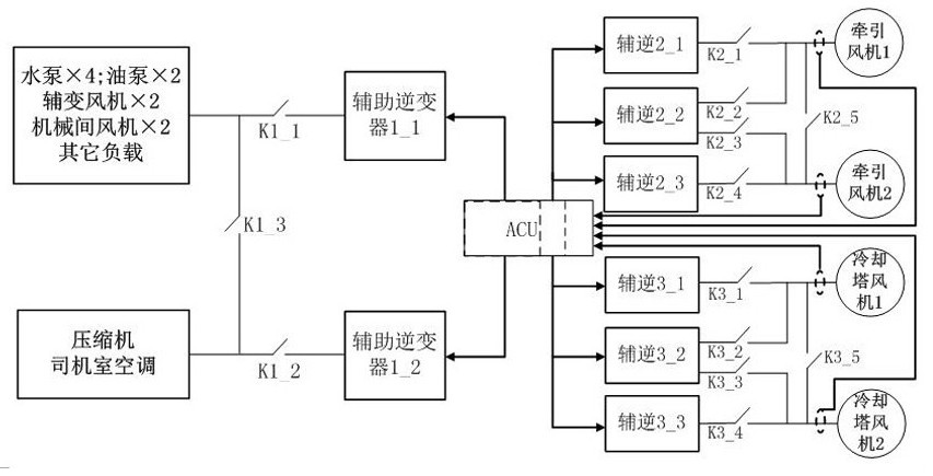
[0013] The topology of auxiliary converters for locomotives is composed of three groups of auxiliary inverters. The second group of auxiliary inverters includes auxiliary inverter 2_1 and auxiliary inverter 2_3, which supply power for traction fan 1 and traction fan 2 respectively. Fan 1 and traction fan 2 adopt a high-performance vector control strategy; the third group of auxiliary inverters includes auxiliary inverter 3_1 and auxiliary inverter 3_3, which supply power for cooling tower fan 1 and cooling tower fan 2 respectively, and cooling tower fan 1. Cooling tower fan 2 adopts a high-performance vector control strategy; the first group of auxiliary inverters supplies power to other loads except traction fan 1, traction fan 2, cooling tower fan 1, and cooling tower fan 2. Traction fan 1, traction fan 2, cooling tower fan 1, and cooling tower fan 2 are replaced with more efficient permanent magnet synchronous motors or permanent magnet assisted synchronous reluctance motors...


PUM


Abstract

The invention relates to a locomotive power supply topological structure, in particular to a topological structure of an auxiliary converter for a locomotive. The topological structure solves the problems of low motor efficiency and power factor caused by the fact that an existing auxiliary converter for an electric locomotive adopts a topological structure that one inverter is provided with a plurality of asynchronous motors, and low efficiency of the asynchronous motors due to the fact that fans in auxiliary equipment of the electric locomotive adopt the asynchronous motors. The topologicalstructure of the auxiliary converter for the locomotive is composed of three sets of auxiliary inverters, wherein the second set of auxiliary inverters supply power to a traction fan 1 and a tractionfan 2 respectively, and the traction fan 1 and the traction fan 2 adopt a high-performance vector control strategy; the third group of auxiliary inverters respectively supply power to a cooling towerfan 1 and a cooling tower fan 2, and the cooling tower fan 1 and the cooling tower fan 2 adopt a high-performance vector control strategy; and the traction fan 1, the traction fan 2, the cooling towerfan 1 and the cooling tower fan 2 are replaced with permanent magnet synchronous motors or permanent magnet auxiliary synchronous reluctance motors.

Description

technical field [0001] The invention relates to a locomotive power supply topology, in particular to a locomotive auxiliary converter topology. Background technique [0002] The load of electric locomotive mainly includes two parts: traction motor and auxiliary equipment. The traction motor mainly provides power for the locomotive, and is powered by the traction converter; auxiliary equipment mainly includes fans (traction fans, cooling tower fans, auxiliary transformer fans, machinery room fans), pumps (water pumps, oil pumps) and some living areas. Electrical equipment (cab air conditioner, compressor). Existing electric locomotives often contain two auxiliary inverters to supply power to auxiliary equipment. Auxiliary inverters take power from the intermediate DC link of the traction converter, one works in constant voltage and fixed frequency mode, and supplies power to three-phase AC380V loads including living areas and some smaller power fans and pump loads, and the ...

Claims


Application Information

Patent Timeline
IPC IPC(8): H02P27/06H02P6/04H02P25/024H02P25/08H02P25/092H02P21/00F04D27/00
CPCH02P27/06H02P6/04H02P25/024H02P25/08H02P25/092H02P21/00H02P27/047F04D27/00F04D27/004H02P2207/05
Inventor 张瑞峰丁志勇詹哲军梁海刚贺志学
Owner CRRC YONGJI ELECTRIC CO LTD
Learn More