
A hybrid transmission case clutch oil circuit structure

A technology for clutches and transmissions, which is applied to clutches, hybrid vehicles, motor vehicles, etc., can solve the problems of increasing the outer contour size of the transmission, occupying the outer space of the transmission, and being unfavorable for miniaturization, etc., so as to reduce the outer contour size and simplify Assembly process, effect of reducing the risk of oil leakage

Active Publication Date: 2022-07-05
CHONGQING CHANGAN AUTOMOBILE CO LTD
View PDF24 Cites 0 Cited by
  • Summary
  • Abstract
  • Description
  • Claims
  • Application Information

AI Technical Summary

Problems solved by technology

[0002] P2 type hybrid is a kind of arrangement of hybrid power system, which realizes the power switching between various modes through a separate clutch, which is called K0 clutch, and the hybrid transmission controls the combination of the motor and the input shaft through the K0 clutch. The clutch is separated, while the control and lubrication of the clutch are realized through the transmission oil circuit. At present, the clutch lubrication and control oil circuit of hybrid transmissions are mostly connected by external separate oil pipes, and oil circuit conversion parts need to be added. The longer the length, the more parts there are, the more risk points of external oil leakage. Once the oil leaks, customers will complain; there are many assembly parts, the installation steps are complicated, and the assembly process is increased, thereby increasing the cost; the external pipeline occupies the outer space of the transmission, which increases the size of the transmission. Outline dimensions, not conducive to miniaturization

Method used


Image

  • A hybrid transmission case clutch oil circuit structure
  • A hybrid transmission case clutch oil circuit structure
  • A hybrid transmission case clutch oil circuit structure

Examples


Embodiment Construction

[0024] The specific embodiments of the present invention will be further described below with reference to the accompanying drawings.

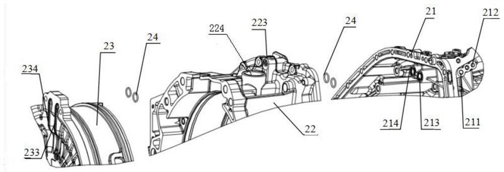
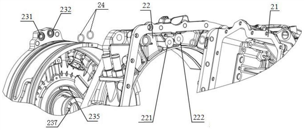
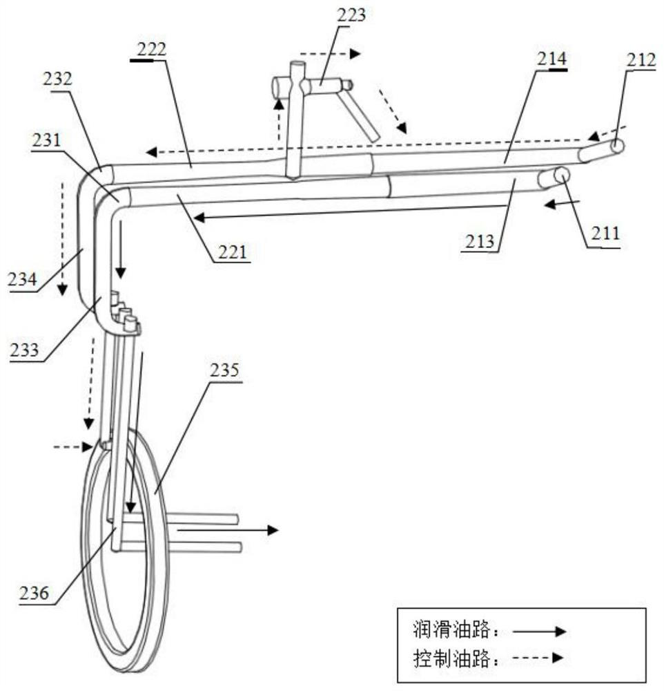
[0025] see Figure 1 to Figure 4 As shown, this embodiment discloses a hybrid transmission case clutch oil circuit structure, including a left case 21, a right case 22 and a P2 housing 23; the left case 21 is provided with a left case clutch lubricating oil inside the housing 213 and the left case clutch control oil passage 214; the right case housing is provided with the right case clutch lubricating oil passage 221 and the right case clutch control oil passage 222; the P2 case 23 is provided with the P2 case clutch control oil passage 234 and P2 shell clutch lubricating oil passages; the oil inlet 211 of the left case clutch lubricating oil passage is used to communicate with the lubricating oil outlet of the hydraulic module 25, and the oil outlet of the left casing clutch lubricating oil passage 213 is connected to the right case. The oil...


PUM


Abstract

The invention discloses a clutch oil circuit structure of a hybrid transmission case body, which comprises a left case body, a right case body and a P2 shell; The oil outlet of the case clutch lubricating oil passage is communicated with the oil inlet of the right case clutch lubricating oil passage; the oil outlet of the right casing clutch lubricating oil passage is communicated with the oil inlet of the P2 shell clutch lubricating oil passage, The oil outlet of the lubricating oil passage of the P2 shell clutch is set on the shaft hole of the P2 casing; the oil inlet of the left casing clutch control oil passage is connected with the pressure oil outlet of the hydraulic module, and the left casing clutch controls the oil outlet of the oil passage The port is connected with the oil inlet of the right case clutch control oil passage, the oil outlet of the right case clutch control oil passage is connected with the oil inlet of the P2 case clutch control oil passage, and the oil outlet of the P2 case clutch control oil passage is connected with the oil outlet of the P2 case clutch control oil passage. The clutch piston chambers communicate. The oil circuit structure reduces the risk of transmission oil leakage and improves customer satisfaction.

Description

technical field [0001] The invention relates to the technical field of hybrid transmissions, in particular to a clutch oil circuit structure of a hybrid transmission case. Background technique [0002] The P2 hybrid is an arrangement of the hybrid system, which realizes the power switching between the various modes through a separate clutch, which is called the K0 clutch. The hybrid transmission controls the combination of the motor and the input shaft through the K0 clutch. The clutch is separated, and the control and lubrication of the clutch are realized through the transmission oil circuit. At present, the clutch lubrication and control oil circuit of the hybrid transmission is mostly connected by an external separate oil pipe, and it is necessary to increase the oil circuit conversion parts. Longer, the more parts there are, the more risk points of external oil leakage, and once the oil leaks, customers will complain; there are many assembly parts, the installation step...

Claims


Application Information

Patent Timeline
Patent Type & Authority Patents(China)
IPC IPC(8): F16H57/04F16D48/02F16H61/40
CPCF16H57/0424F16D48/02F16H61/40F16D2048/0224Y02T10/62
Inventor 张晓蛟陈瑞余洪周元聪付亮
Owner CHONGQING CHANGAN AUTOMOBILE CO LTD
Learn More