A device and method for depositing pure DLC by graphite cathode arc enhanced glow discharge

A technology of graphite cathode and glow discharge, applied in vacuum evaporation plating, coating, gaseous chemical plating, etc., can solve problems such as metal element pollution, achieve quality assurance, easy film composition and performance, and low cost Effect

Active Publication Date: 2022-06-24
HARBIN INST OF TECH
View PDF14 Cites 0 Cited by
  • Summary
  • Abstract
  • Description
  • Claims
  • Application Information

AI Technical Summary

Problems solved by technology

[0009] The purpose of the present invention is to solve the problem of "pollution" of DLC by metal elements when the existing metal cathode arc enhanced glow discharge is used to prepare DLC, and to provide a device and method for depositing pure DLC by graphite cathode arc enhanced glow discharge

Method used


Image

  • A device and method for depositing pure DLC by graphite cathode arc enhanced glow discharge
  • A device and method for depositing pure DLC by graphite cathode arc enhanced glow discharge
  • A device and method for depositing pure DLC by graphite cathode arc enhanced glow discharge

Examples


specific Embodiment approach 1

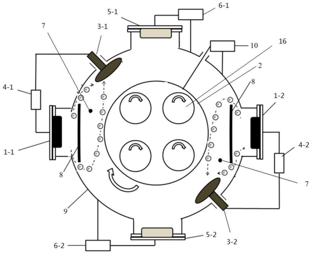
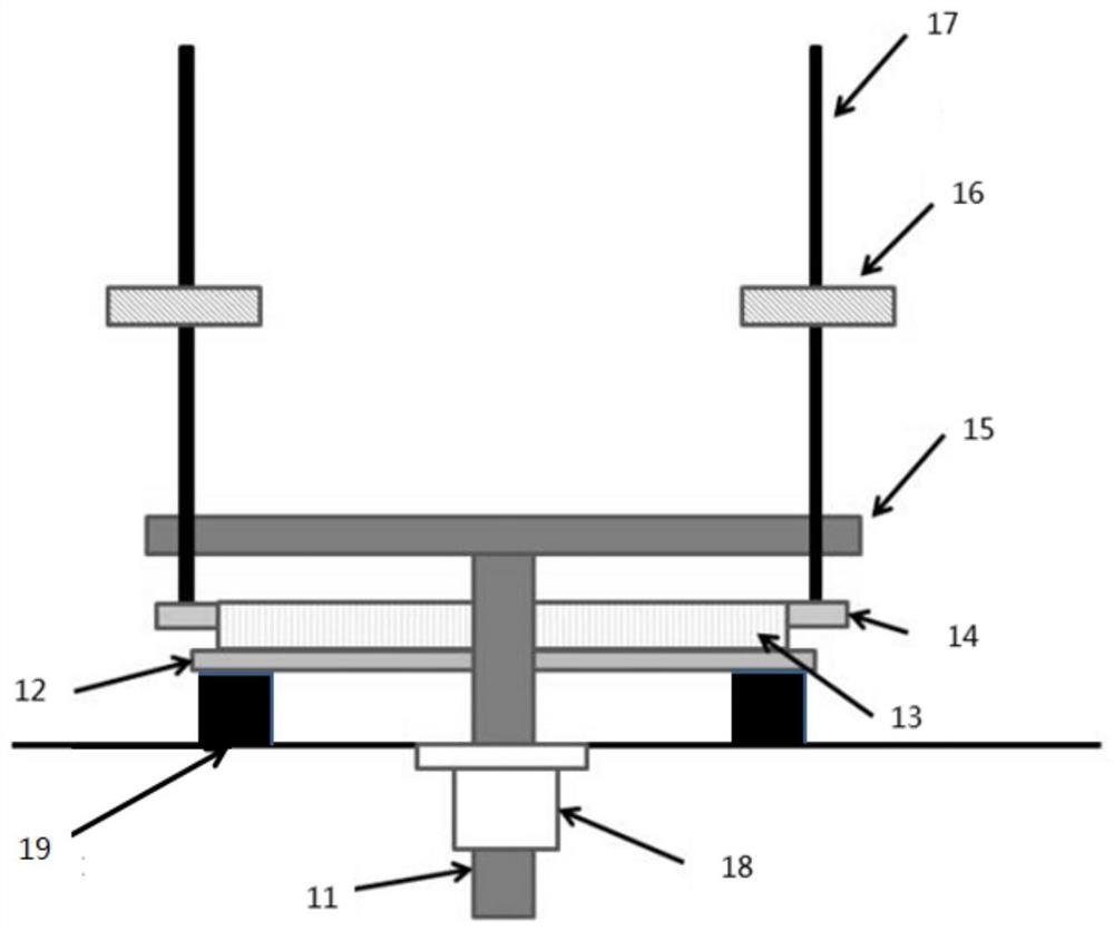
[0029]Embodiment 1: In this embodiment, a graphite cathode arc-enhanced glow discharge deposition pure DLC device includes a vacuum chamber 9, a turret 2, a bias power supply 10, a first graphite cathode arc 1-1, and a second graphite cathode arc 1-2. First metal cathode 5-1, second metal cathode 5-2, first anode 3-1, second anode 3-2, first high pulse power supply 4-1, second high pulse power supply 4- 2. The first DC power supply 6-1 and the second DC power supply 6-2; the bottom of the vacuum chamber 9 is provided with an air inlet 7; , four flanges are evenly arranged on the wall of the vacuum chamber 9 along the circumferential direction, and the four flanges are respectively fixedly connected to the first graphite cathode arc 1-1, the first metal cathode 5-1, and the second graphite cathode arc 1-2 And the second metal cathode 5-2; the first graphite cathode arc 1-1 and the second graphite cathode arc 1-2 and the turret 2 are provided with a baffle 8, and the two ends of...

specific Embodiment approach 2

[0031] Embodiment 2: The difference between this embodiment and Embodiment 1 is that the turret 2, the first graphite cathode arc 1-1, the second graphite cathode arc 1-2, the first metal cathode 5-1, and the second metal cathode The cathode 5 - 2 , the first anode 3 - 1 , the second anode 3 - 2 , and the baffle 8 are all insulated from the vacuum chamber 9 . Others are the same as the first embodiment.

[0032] In this embodiment, the turret 2, the first graphite cathode arc 1-1, the second graphite cathode arc 1-2, the first metal cathode 5-1, the second metal cathode 5-2, the first anode 3-1, the second The anode 3-2 and the baffle 8 are insulated from the vacuum chamber 9 by polytetrafluoroethylene.

specific Embodiment approach 3

[0033] Embodiment 3: The difference between this embodiment and Embodiment 1 or 2 is that the electrical connection terminal of the first anode 3-1 is electrically connected to the positive electrode of the first high-pulse power supply 4-1, and the first high-pulse power supply 4- The negative pole of 1 is electrically connected to the electrical connection terminal of the first graphite cathode arc 1-1; the electrical connection terminal of the second anode 3-2 is electrically connected to the positive pole of the second high-pulse power supply 4-2, and the second high-pulse power supply 4- The negative electrode of 2 is electrically connected to the electrical connection end of the second graphite cathode arc 1-2. Others are the same as in the first or second embodiment.


PUM


Abstract

A device and method for depositing pure DLC by graphite cathode arc enhanced glow discharge, and the invention relates to a device and method for pure DLC deposited by graphite cathode arc enhanced glow discharge. The purpose of the present invention is to solve the problem of "pollution" of DLC by metal elements when the existing metal cathode arc enhances glow discharge to prepare DLC. The incoming carbon-containing gas is ionized by the high-density electrons emitted by the graphite cathode arc, and deposited on the surface of the workpiece to form pure DLC. The ratio of ions to atoms in carbon-containing plasmas can be controlled by changing the discharge pattern between the cathode and anode and by adjusting the discharge parameters. The invention avoids the adverse effect of metal doping on the tribological performance when the metal target enhances the glow discharge to prepare the DLC. The invention is applied to the field of preparing DLC ​​by plasma enhanced chemical vapor deposition.

Description

technical field [0001] The invention relates to a device and a method for a graphite cathode arc enhanced glow discharge deposition pure DLC. Background technique [0002] DLC (Diamond-like carbon) films have been widely used due to their low friction coefficient, high hardness, good wear resistance and chemical inertness, such as auto parts, seawater corrosion resistance of ship hulls, and processing of aluminum alloys. [0003] There are many methods for depositing DLC, mainly based on plasma chemical vapor deposition (PECVD). The most widely used method in industry is the method of self-glow discharge of workpieces. This method uses the workpiece itself as the discharge source, and applies medium and high frequency bias on it, and the bias is generally higher than -300V. This method has the following problems: 1. It is greatly affected by the shape of the workpiece and the amount of furnace loading. If the workpiece changes, the process needs to be re-adjusted; 2. The s...

Claims


Application Information

Patent Timeline
Patent Type & Authority Patents(China)
IPC IPC(8): C23C16/26C23C16/503C23C16/515C23C16/517C23C14/16C23C14/06
CPCC23C16/26C23C16/503C23C16/515C23C16/517C23C14/16C23C14/0641C23C14/0664C23C14/0605C23C14/0021
Inventor 田修波胡健巩春志
Owner HARBIN INST OF TECH
Why Eureka
Try Eureka