
Multi-path optical switch synchronous rapid switching control system and control method thereof

A control system and fast switching technology, applied in the field of optical detection, can solve the problems that the electromagnet cannot meet the system time response requirements, the service life limit, the long response time, etc., and achieve the effect of reducing the waiting time of the optical switch operation.

Pending Publication Date: 2020-10-02
HEFEI ZHICHANG PHOTOELECTRIC TECH
View PDF0 Cites 2 Cited by
  • Summary
  • Abstract
  • Description
  • Claims
  • Application Information

AI Technical Summary

Problems solved by technology

[0003] Disadvantages of existing optical path switches: At present, a considerable part of optical path applications use electromagnets as optical switches. The disadvantages are that the response time is long and the service life is limited. response request
[0004] Disadvantages of the existing optical switch control system: the optical switch control method of the electromagnet is relatively simple, and the switch of the optical switch is controlled by a general-purpose input and output circuit. The disadvantage is that the real-time state of the optical switch during the movement cannot be monitored

Method used


Image

  • Multi-path optical switch synchronous rapid switching control system and control method thereof
  • Multi-path optical switch synchronous rapid switching control system and control method thereof
  • Multi-path optical switch synchronous rapid switching control system and control method thereof

Examples


Embodiment Construction

[0026] The following will clearly and completely describe the technical solutions in the embodiments of the present invention with reference to the accompanying drawings in the embodiments of the present invention. Obviously, the described embodiments are only some, not all, embodiments of the present invention. Based on the embodiments of the present invention, all other embodiments obtained by persons of ordinary skill in the art without making creative efforts belong to the protection scope of the present invention.

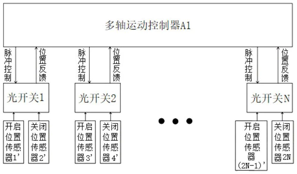
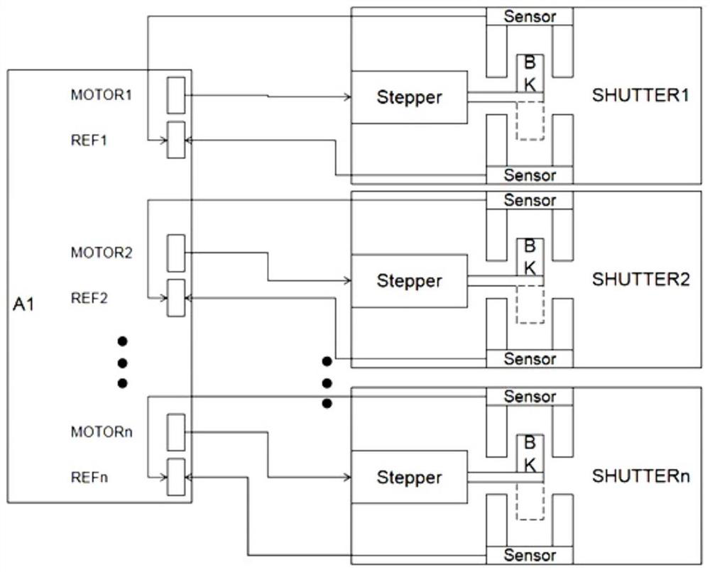
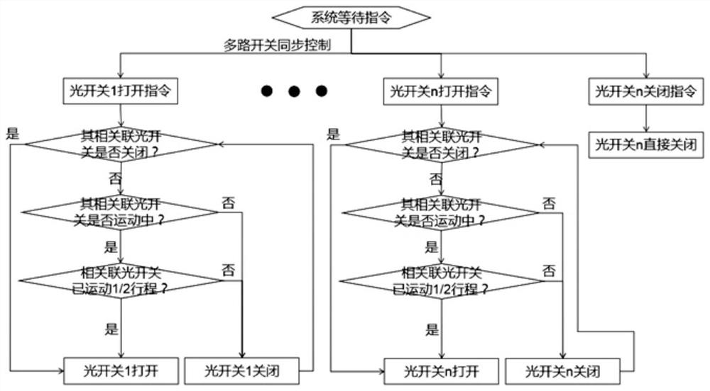
[0027] See figure 1 and figure 2 , a multi-channel optical switch synchronous fast switching control system, including a multi-axis motion controller A1, multiple optical switches, and a position sensor set on each optical switch, each optical switch is integrated with two positions Sensor, the two position sensors are open position sensor and closed position sensor, each optical switch includes a micro stepper motor Stepper and a baffle BK connected to the ...


PUM


Abstract

The invention discloses a multi-path optical switch synchronous rapid switching control system and a control method thereof. The multi-path optical switch synchronous rapid switching control system comprises a multi-axis motion controller, a plurality of optical switches, opening position sensors and closing position sensors, wherein the opening position sensors and the closing position sensors are arranged on the optical switches respectively. Each optical switch comprises a driving motor and a blocking piece connected to a transmission shaft of the driving motor, the blocking pieces are usedfor blocking laser beams, and the driving motor of each optical switch, the opening position sensor on each optical switch and the closing position sensor on each optical switch are connected with the multi-axis motion controller. According to the invention, a micro driving motor is used as a moving body of the blocking pieces of the optical switches, a position sensor is arranged at each of theopening position and the closing position of each optical switch, and the high-speed multi-axis motion controller is adopted to accurately control the motion distance of each optical switch with high-speed pulse, so that the multi-path optical switch has the characteristics of quick response, accurate positioning and high synchronism.

Description

technical field [0001] The invention relates to the field of optical detection, in particular to a multi-channel optical switch synchronous fast switching control system and a control method thereof. Background technique [0002] With the development of optical detection technology, the optical path in the optical design is becoming more and more complex, and the number of optical path switches is increasing. At the same time, the response performance of the optical switch is also required to be higher. An optical switch control system is designed to synchronously control multiple optical switches, and an optical switch with a micro-motor as the main body is designed, which can quickly respond to the motion requirements and precise positioning of the control system. [0003] Disadvantages of existing optical path switches: At present, a considerable part of optical path applications use electromagnets as optical switches. The disadvantages are that the response time is long ...

Claims


Application Information

Patent Timeline
Patent Type & Authority Applications(China)
IPC IPC(8): G01D5/30G02B26/00
CPCG01D5/305G02B26/00
Inventor 周海峰俞伟洋陈坚吴周令
Owner HEFEI ZHICHANG PHOTOELECTRIC TECH
Learn More