Direct injection molding equipment for reinforced particles

A technology of injection molding and particles, applied in the field of injection molding, can solve the problems of increasing production cost, low production flexibility, adding modified granulation parts, etc., to achieve the effect of reducing production cost, improving comprehensive performance, and increasing feeding amount

Pending Publication Date: 2020-10-02
GUANGDONG YIZUMI PRECISION MACHINERY
View PDF0 Cites 0 Cited by
  • Summary
  • Abstract
  • Description
  • Claims
  • Application Information

AI Technical Summary

Problems solved by technology

However, this two-step method has the following defects: 1. The modified granulation part is added, resulting in increased equipment investment, energy consumption, and raw material transportation and storage; 2. Generally, reinforced particles (fiber or powder) pass through common feeding equipment, and the feeding effect is reduced. Difficult and low efficiency; 3. The modified manufacturer can only provide the specified content of pellets. If the content of reinforced particles needs to be changed, the processor needs to mix with the unreinforced matrix, which puts additional requirements on the equipment and material supply system, which will undoubtedly increase Cost of production
It can be seen that the traditional two-step molding method has high material costs, low production flexibility, and complicated customized materials. This method cannot represent the future development trend

Method used


Image

  • Direct injection molding equipment for reinforced particles
  • Direct injection molding equipment for reinforced particles
  • Direct injection molding equipment for reinforced particles

Examples


Embodiment Construction

[0018] The present invention will be further described below in conjunction with the accompanying drawings and embodiments.

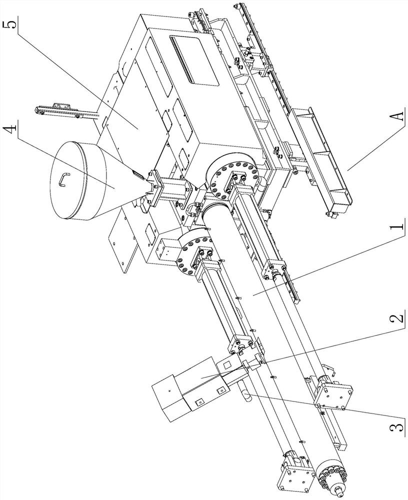
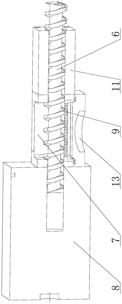
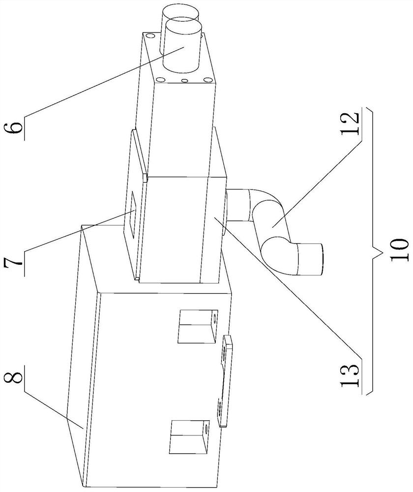
[0019] see Figure 1-Figure 4 , the reinforced particle direct injection molding equipment, taking the injection molding machine as an example, includes a feeding device A, and the feeding device A includes a power system 5, a plasticizing device 1, a feeding system 4, a reinforced particle forced feeding device 2 and a vacuum auxiliary Device 3, the power system 5 is connected with the plasticizing device 1, the feeding system 4 is arranged at the tail end of the plasticizing device 1, the reinforced particle forced feeding device 2 is arranged at the front end of the plasticizing device 1, the vacuum auxiliary device 3 is connected with the reinforced particle The forced feeding device 2 is connected. When the injection molding machine is working, the plastic matrix enters the plasticizing device 1 through the feeding system 4, the reinforced particl...


PUM

PropertyMeasurementUnit
thicknessaaaaaaaaaa
thicknessaaaaaaaaaa

Abstract

The invention discloses direct injection molding equipment for reinforced particles. The direct injection molding equipment for the reinforced particles comprises a feeding device, the feeding devicecomprises a power system, a plasticizing device, a discharging system, a reinforced particle forced feeding device and a vacuum auxiliary device, the power system is connected with the plasticizing device, the discharging system is arranged at the tail end of the plasticizing device, the reinforced particle forced feeding device is arranged at the front end of the plasticizing device, and the vacuum auxiliary device is connected with the reinforced particle forced feeding device. The direct injection molding equipment for the reinforced particles has the following beneficial effects that 1, anintermediate granulation process is omitted, so that the energy consumption is reduced; 2, fibers are added at the front end of an injection molding system so that the stroke and stress in an injection molding material barrel can be reduced, the length of the fibers in a product cam be reserved to the maximum extent, and the comprehensive performance of the composite material can be improved to the maximum extent; and 3, the fiber content or length can be changed and can be directly completed on the injection molding equipment, and redundant raw material is not required to be stored or an extruder is not required to be purchased additionally, so that the production cost is greatly reduced.

Description

technical field [0001] The invention relates to the technical field of injection molding, in particular to a direct injection molding equipment for reinforcing particles. Background technique [0002] Traditional reinforced plastic products are mainly formed by a two-step method. The first step is to granulate the plastic matrix and reinforced particles (fiber or powder, etc.) through a pultrusion process to obtain plastic particles. final product. However, this two-step method has the following defects: 1. The modified granulation part is added, resulting in increased equipment investment, energy consumption, and raw material transportation and storage; 2. Generally, reinforced particles (fiber or powder) pass through common feeding equipment, and the feeding effect is reduced. Difficult and low efficiency; 3. The modified manufacturer can only provide the specified content of pellets. If the content of reinforced particles needs to be changed, the processor needs to mix w...

Claims


Application Information

Patent Timeline
Patent Type & Authority Applications(China)
IPC IPC(8): B29C48/25B29C48/285B29C48/395B29C48/40B29C48/68B29C48/69B29C48/14
CPCB29C48/14B29C48/252B29C48/285B29C48/397B29C48/40B29C48/681B29C48/682B29C48/69
Inventor 姚华陈炽辉邓祖作
Owner GUANGDONG YIZUMI PRECISION MACHINERY
Why Eureka
Try Eureka