
Method for Manufacturing a Sheet Product for Use in a Dispenser and Strip of Sheet Product

a technology of sheet product and dispenser, which is applied in the direction of paper/cardboard containers, identification devices, instruments, etc., can solve the problems of inconvenient overall process of removing paper sheets from dispensers, risk of paper breaking, and inability to provide sheets to users, so as to reduce the perforation breaking strength of the strips of sheet products, reduce the risk of paper breaking, and reduce the effect of the manufacturing process

Active Publication Date: 2012-09-20
GPCP IP HLDG LLC
View PDF2 Cites 26 Cited by
  • Summary
  • Abstract
  • Description
  • Claims
  • Application Information

AI Technical Summary

Benefits of technology

[0029]It is one intention of the above method for manufacturing strips of sheet product to provide for a reduction in the perforation breaking strength of the strips of sheet product while not adversely affecting the production constraints of the manufacturing process, more specifically, to provide for a decreased breaking strength of the strips of sheet product while maintaining the yield and throughput of the production of the strips from a web of sheet product while providing a web product that provides for high or higher speed production rates relative to a sheet product with continuous perforations extending across the entire web.
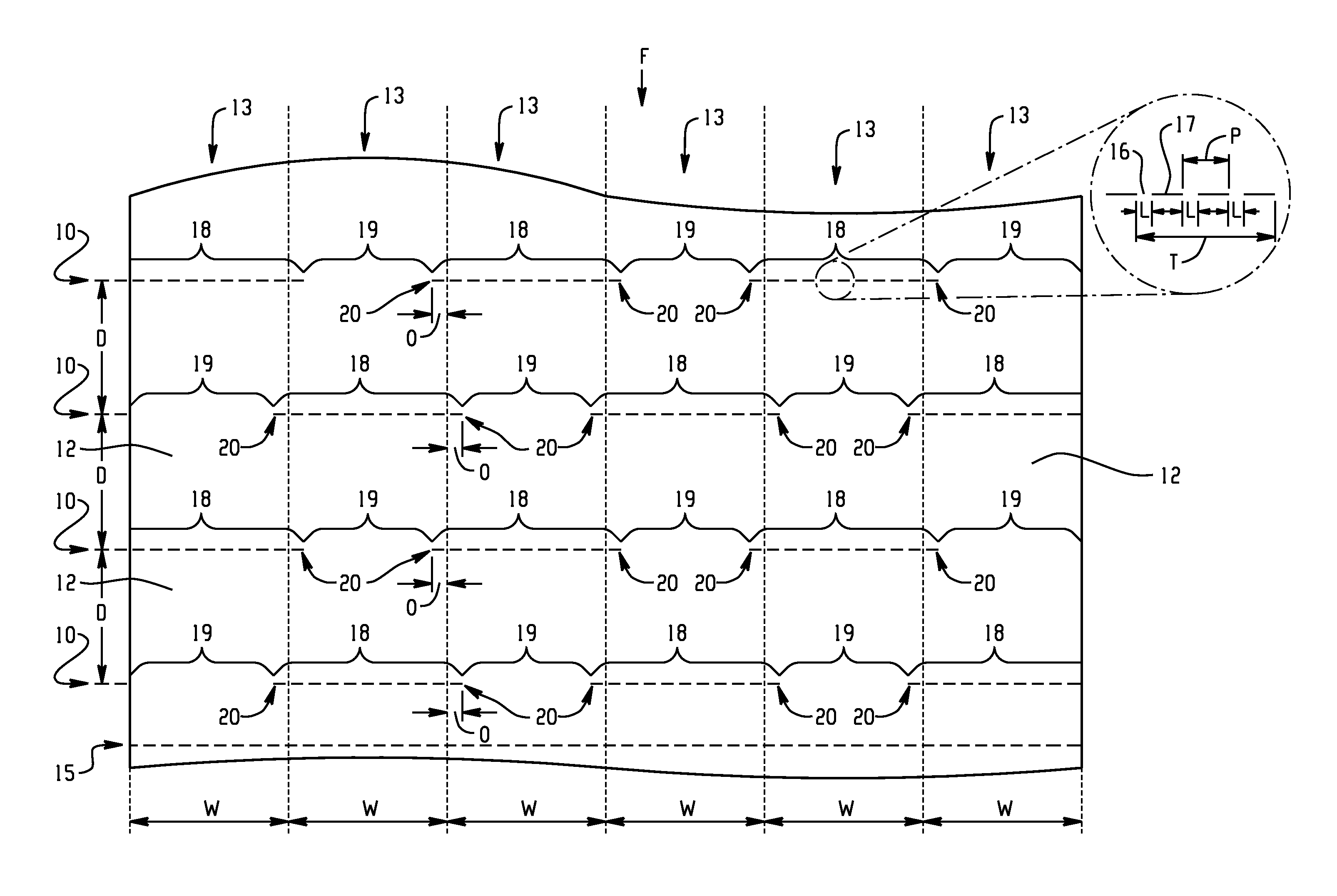
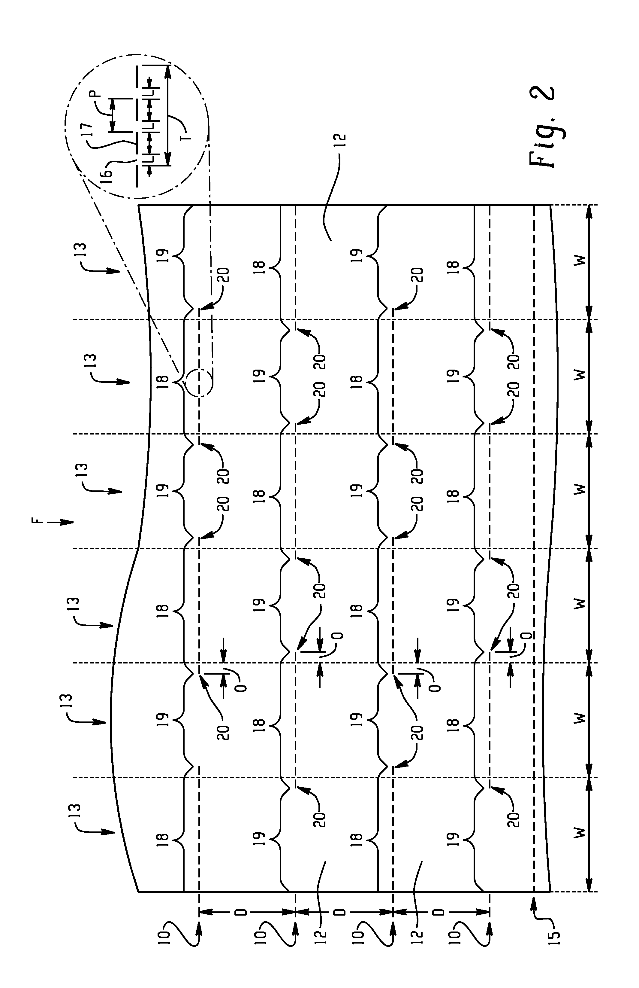
[0030]Stated another way, the method of manufacturing a web of sheet product according to the present invention provides for an increase in the breaking strength of the web of sheet product while feeding relative to a sheet product with continuous perforations extending across the entire web, thereby reducing the risk of breaking and maintaining the yield and throughput of the production of the perforated web as an intermediate product. To overcome the risk of breaking of the web while feeding it between the stages of creating the perforation lines and, e.g., reeling the web to obtain a log, perforated segments are only present along a portion of the perforation line. Hence, the web is partially perforated along each perforation line, wherein perforated segments and non-cut segments are alternately arranged along the perforation line. This is achieved by cutting the perforations in segments having a smaller width than the web to be processed, such that the perforations are cut only partially across the overall width of the web. The breaking strength of the fed web is increased and the tension load in the machine feeding direction of the web, which is necessary for achieving a sufficient density of sheet product on the log, is thereby substantially borne by the non-cut segment(s) along the perforation line. Moreover, as the breaking strength is increased, the above method allows for increased machine feed speed and has a positive impact on the throughput of the manufacturing process. Desirably, the web machine feed speed is at least 300 ft / min in the present invention.

Problems solved by technology

Furthermore, it should be assured that the sheets do not break along a perforation line that is still within the housing, or else operation of the dispenser is compromised and sheets are unavailable to the user.
When applying the pulling force, there is always the risk of breaking of the paper, in particular, at the points where the perforation lines separate the respective paper sheets.
The necessary perforation breaking force threshold of current sheets and dispensers requires the user to pull the sheet with a significant force, which can render the overall process of withdrawing a paper sheet from the dispenser inconvenient.
The desire to reduce the breaking force threshold of the perforation lines of the paper strip conflicts with the desire to increase or maintain the machine feeding speed, and raises significant issues in the manufacturing process.
A high perforation (i.e., low bond ratio) and resulting low breaking force threshold could lead to breakage of the perforated paper web in the manufacturing process when the paper web is transferred to the reels to form a paper roll, especially when such a transfer is done at high speed and / or tension.

Method used


Image

  • Method for Manufacturing a Sheet Product for Use in a Dispenser and Strip of Sheet Product
  • Method for Manufacturing a Sheet Product for Use in a Dispenser and Strip of Sheet Product
  • Method for Manufacturing a Sheet Product for Use in a Dispenser and Strip of Sheet Product

Examples


Embodiment Construction

[0048]Reference in detail will now be made to non-limiting embodiments of the invention, examples of which are illustrated in the accompanying drawings. Wherever possible, the same reference number has been used throughout the drawings and the following detailed description to refer to the same or similar parts.

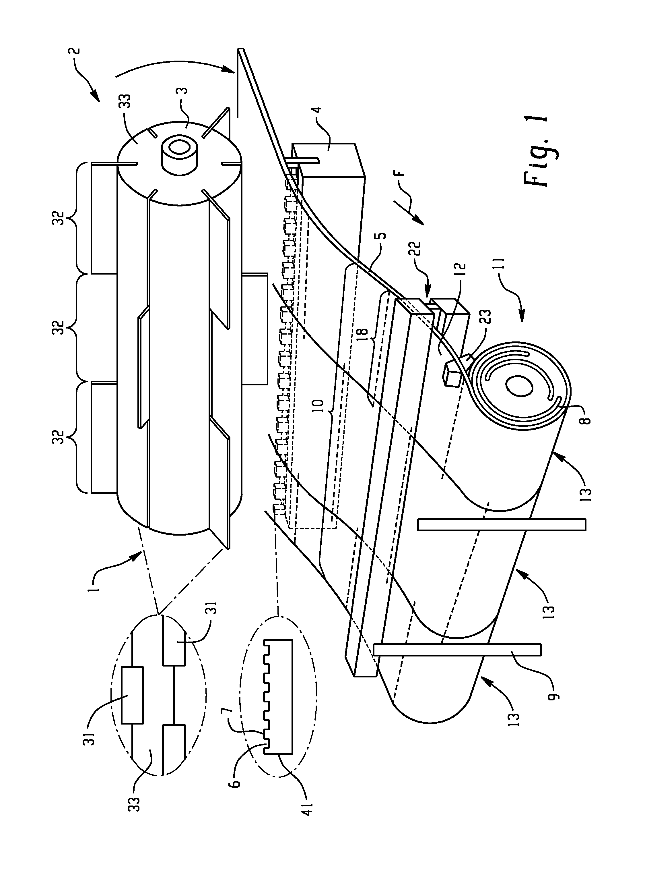
[0049]FIG. 1 is a schematic representation of a portion of a manufacturing system 1 for producing a roll of sheet product from a basic web 5 of sheet product and further illustrates a method for manufacturing strips 13 of sheet product. The web of sheet product may, e.g., be a paper web 5 made of absorbent paper used for paper towels, napkins, hand tissues, facial tissues, toilet papers, kitchen towels, hand towels, wipers, placemats, and the like. As an alternative to paper, any woven or non-woven absorbent material that is suitable to serve as a cleaning or drying sheet, or any non-absorbent material that is suitable to serve as a cleaning or drying sheet may be used. FIG. ...


PUM

PropertyMeasurementUnit
web machine feed speedaaaaaaaaaa
feed speedaaaaaaaaaa
total lengthaaaaaaaaaa

Abstract

The invention relates to a method of manufacturing a web of sheet product, with a discontinuous perforation arrangement such that manufacture of a web of sheet product provides for an increase in the breaking strength of the web of sheet product while feeding the web in a machine direction, thereby reducing the risk of breaking and maintaining the yield and throughput of the production of the perforated web as an intermediate product, yet providing a low breaking force for individual strips produced from the web.

Description

CROSS-REFERENCE TO RELATED APPLICATIONS[0001]This application is a continuation-in-part application of U.S. patent application Ser. No. 12 / 513,004, filed on Apr. 30, 2009, which is the national stage entry of International Application No. PCT / FR2007 / 001737, filed on Oct. 22, 2007, which claims priority to French Application No. 06 09546, filed on Oct. 31, 2006 (now French Patent No. 2907654), the priorities of which are hereby claimed and their disclosures incorporated in their entireties herein by reference.TECHNICAL FIELD[0002]The present application generally relates to a method for efficiently manufacturing a strip of sheet product for use in dispensers, in particular for manufacturing rolls of an absorbent or non-absorbent product, such as paper towels, napkins, hand tissues, facial tissues, toilet papers, kitchen towels, wipers, placemats, and the like. Furthermore, the present application relates to a strip of sheet product for use in a dispenser.RELATED ART[0003]Manually ope...

Claims


Application Information

Patent Timeline
Patent Type & Authority Applications(United States)
IPC IPC(8): B32B3/24B31B49/00B31B50/00
CPCB31D1/0031Y10T428/15B31D1/04A47K10/16Y10T83/483Y10T83/0515A47K10/3612A47K10/42B65H45/142B65H45/18B65H2701/1924B65H45/28B65H31/3009B65H31/02B65H31/10B65H2405/11152B65H2405/11151B65H2551/29B65H33/18B65H33/00B65H2551/15B65H2551/14B26F1/20A47K2010/3668
Inventor CATTACIN, GILLESLAURENT, PIERREMARIETTA-TONDIN, JULIENRUPPEL, REMYANDRES, ANN M.CASE, ABBY C.
Owner GPCP IP HLDG LLC
Learn More