A sealing structure for impeller blade tip of impeller machinery

A technology of impeller machinery and top seal, which is applied in the direction of mechanical equipment, machine/engine, engine components, etc. It can solve the problems of screw seal influence and seal failure, and achieve the effect of increasing resistance, improving service life and improving aerodynamic efficiency

Active Publication Date: 2022-04-19
INST OF ENGINEERING THERMOPHYSICS - CHINESE ACAD OF SCI
View PDF7 Cites 0 Cited by
  • Summary
  • Abstract
  • Description
  • Claims
  • Application Information

AI Technical Summary

Problems solved by technology

However, the spiral seal is greatly affected by the rotor speed, and when the design speed deviates to a certain extent, there is a problem of seal failure.

Method used


Image

  • A sealing structure for impeller blade tip of impeller machinery
  • A sealing structure for impeller blade tip of impeller machinery
  • A sealing structure for impeller blade tip of impeller machinery

Examples


Embodiment Construction

[0027] In order to make the objectives, technical solutions and advantages of the present invention clearer, the technical solutions in the embodiments of the present invention will be described in more detail below in conjunction with the drawings in the embodiments of the present invention. In the drawings, the same or similar reference numerals denote the same or similar elements or elements having the same or similar functions throughout. The described embodiments are some, but not all, embodiments of the invention. The embodiments described below by referring to the figures are exemplary and are intended to explain the present invention and should not be construed as limiting the present invention. Based on the embodiments of the present invention, all other embodiments obtained by persons of ordinary skill in the art without creative efforts fall within the protection scope of the present invention. The structure and technical solutions of the present invention will be ...


PUM


Abstract

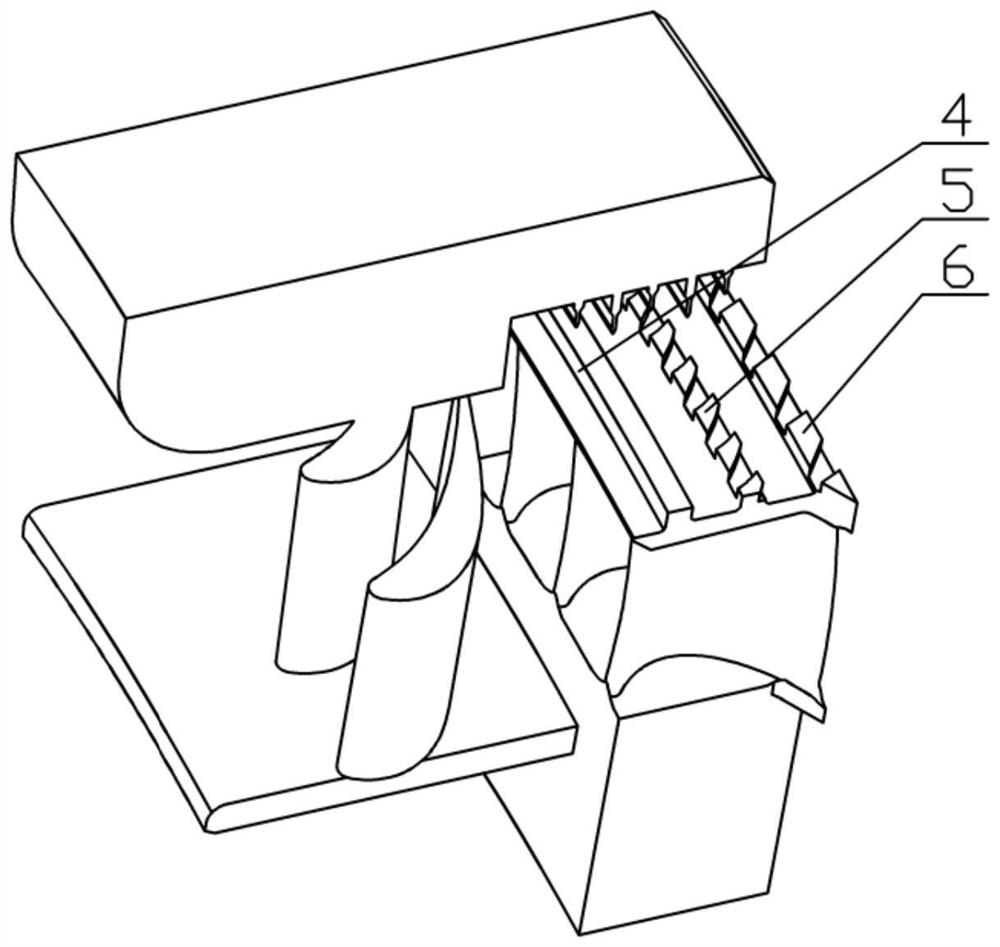
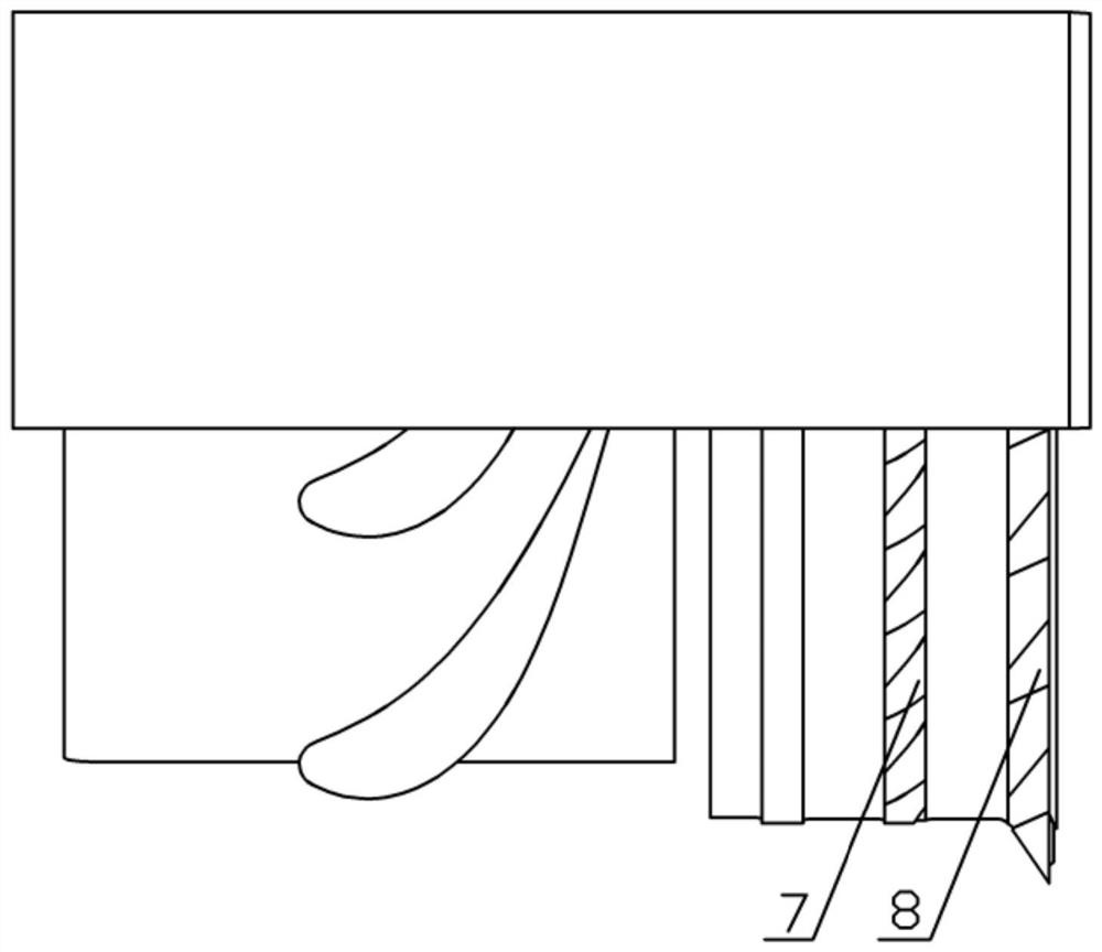
The invention discloses a sealing structure for the top of a moving blade of a turbomachinery, which includes a turbine blade shroud, a sealing tooth and a casing, the first boss on the inlet side of the blade shroud is continuous in the circumferential direction without slots, and other high steps are provided with pumping grooves / hole, the notch is contracted from the exhaust side to the intake side, and forms a certain angle with the centerline of the rotating shaft, so that when the blade rotates, the gap airflow passes through the contracted pumping groove / hole to produce a "pumping effect", thereby Increase the pressure on the air outlet side of the long sealing teeth to reduce the pressure difference on both sides of the gap between the long sealing teeth and reduce leakage. In order to reduce the leakage of the blade tip clearance gas toward the blade tip when the gas is boosted countercurrently along the slot, the slot on the tip of the blade tip is contracted toward the tip of the blade, or an opening is provided on the boss instead of the slot, which can Play a better effect of preventing leakage. Through the application of the above-mentioned sealing structure, the leakage of the tip clearance can be made smaller, thereby reducing the leakage loss of the turbine, and improving the efficiency and economic benefits of the unit.

Description

technical field [0001] The invention relates to the seal structure of the moving blade top of the turbomachinery, specifically a combination sealing structure of a turbine blade top labyrinth and a spiral groove / hole. Top clearance leakage and flow loss, thereby improving the efficiency and economics of the turbine. Background technique [0002] There is a gap between the rotor and the casing of the labyrinth seal, no solid contact, no lubrication, simple maintenance, long service life, no need to use other sealing materials and allow thermal expansion, and can adapt to high temperature, high pressure, high speed frequency occasions, so This type of sealing is widely used in blade tip seals and shaft seals of steam turbines, gas turbines, compressors, blowers and other equipment. The leakage of the labyrinth seal increases with the increase of the gap value and the pressure difference before and after the seal. [0003] The biggest advantage of the spiral groove seal is th...

Claims


Application Information

Patent Timeline
Patent Type & Authority Patents(China)
IPC IPC(8): F01D11/02
CPCF01D11/02F01D11/003
Inventor 李辉陈海生朱阳历李文王星
Owner INST OF ENGINEERING THERMOPHYSICS - CHINESE ACAD OF SCI
Why Eureka
Try Eureka