
Improved rebar straightening frame

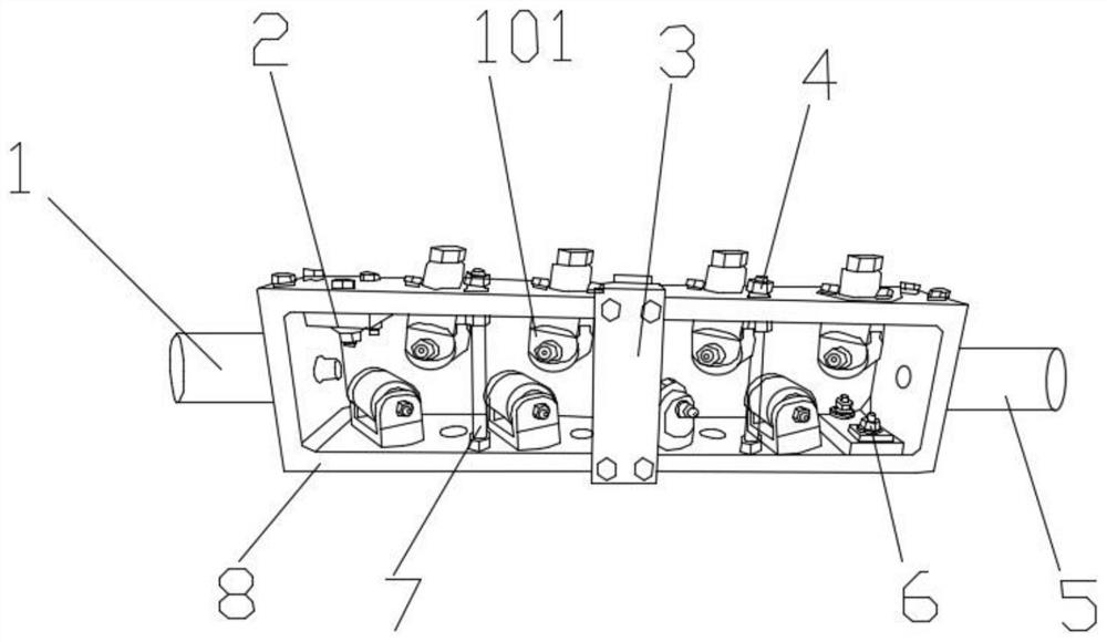
A straightening frame and improved technology, applied in the field of improved steel bar straightening frame, can solve the problems of large straightening centrifugal force, low production efficiency, and deformation of the straightening frame, and achieve the improvement of concentricity and rotational speed, sealing and dustproofing. Good effect, the effect of preventing structural damage

Pending Publication Date: 2020-09-29
范良珍
View PDF0 Cites 0 Cited by
  • Summary
  • Abstract
  • Description
  • Claims
  • Application Information

AI Technical Summary

Problems solved by technology

[0002] At present, the production of stirrups in the construction industry requires straightened steel bars. After the steel bars are straightened, they are manually fed and bent. The labor intensity is high and the production efficiency is low. Later, mechanical equipment is also used for operation. Although bending and hydraulic bending reduce the labor intensity of the operator, there are still problems such as low production efficiency, easy wear of steel bars, high mechanical power, and high energy consumption. Steel bar straightening machines are often used to straighten steel bars, and It can remove the scale on the surface of the steel bar, and the steel bar straightening frame is the main component of the steel bar straightening machine
However, the side of the common straightening frame is set as a disc, and the centrifugal force of the straightening is too large, which increases the wear and tear on the straightening wheel and is easy to be damaged. life

Method used


Image

  • Improved rebar straightening frame
  • Improved rebar straightening frame
  • Improved rebar straightening frame

Examples


Embodiment 1

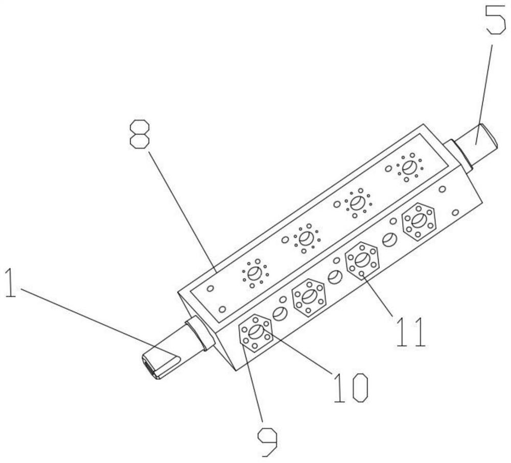
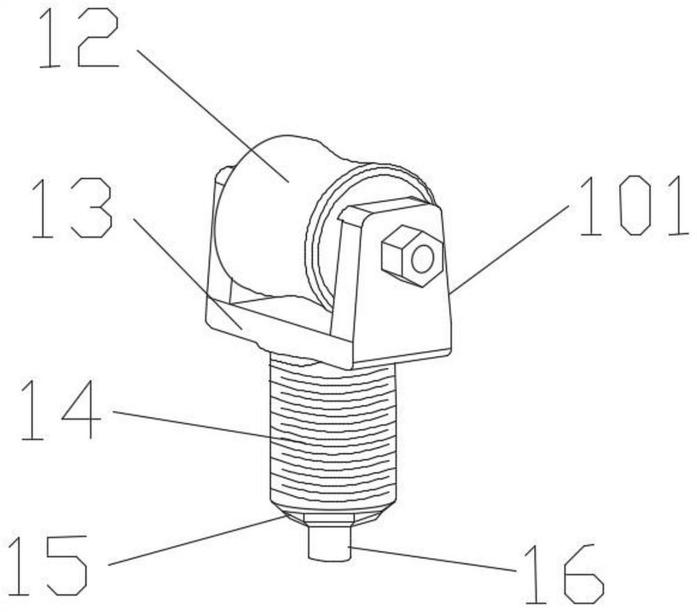
[0028] An improved steel bar straightening frame, including a first connecting pipe 1, a straightening frame body 8, a second connecting pipe 5, a straightening wheel device 101, a reinforcing platen 3, a fixing rod 7, and a milling disc 9, the described The straightening frame frame body 8 is a rectangular frame body with a hollow inside, and the two ends of the narrow side are respectively connected with the first connecting pipe 1 and the second connecting pipe 5; the straightening wheel device 101 is installed in the The inner sides of the frame body 8 of the straightening frame; the reinforcing plate 3 is fixedly installed on both sides of the frame body 8 of the straightening frame; the fixed rod 7 communicates with the frame body 8 of the straightening frame, and is fixedly installed on the On the straightening frame body 8; the milling disk 9 is hexagonal, embedded in the side of the straightening frame body 8, and the inside is provided with a milling disk groove 10 an...

Embodiment 2

[0038] In this embodiment, the main structure of the straightening frame body 8 is the same as that in Embodiment 1, the difference is that a bearing 17 or a gasket 18 is engaged in the inner groove of the wheel cavity on both sides of the straightening wheel 12, and the adjustment There are two bearings 17 or sealing pads 18 engaged on both sides of the straight wheel 12, and the bearings 17 and the sealing pads 18 have the same size and can be replaced with each other. The straightening wheel 12 is fixedly installed on the straightening wheel fixing frame 13 through the screw rod 19; the sealing gasket 18 is cylindrical, the center of the circle is provided with a round hole matching the size of the screw rod 19, and the outer side of the cylinder is provided with a concave groove; the screw rod One end of 19 is provided with an engaging part 21 for clamping with the gasket 18, and the other end is provided with a screw thread to cooperate with the nut; the diameter of the en...


PUM


Abstract

The invention relates to an improved rebar straightening frame. A straightening frame body is a rectangular frame body of which the interior is hollow, and short edges at the two ends are connected with a first connection pipe and a second connection pipe correspondingly. Straightening wheel devices penetrate through milling discs to be fixedly installed on the two sides of the interior of the straightening frame body. Reinforcement pressing plates are fixedly installed on the upper side and the lower side of the straightening frame body. Fixing rods penetrate through the straightening frame body and are fixedly installed on the straightening frame body through first nuts. The milling discs are hexagonal, are embedded in the side surfaces of the straightening frame body and are internallyprovided with milling disc grooves and fixing holes. The improved rebar straightening frame is high in practicality and simple in structure, discs on the side surfaces of the straightening frame are replaced with the hexagonal milling discs, the straightening centrifugal force is reduced, the concentricity of rebar straightening and the rotation speed are improved, and meanwhile, the straighteningframe body is reinforced.

Description

technical field [0001] The invention relates to the field of improved steel bar straightening frames, in particular to an improved steel bar straightening frame. Background technique [0002] At present, the production of stirrups in the construction industry requires straightened steel bars. After the steel bars are straightened, they are manually fed and bent. The labor intensity is high and the production efficiency is low. Later, mechanical equipment is also used for operation. Although bending and hydraulic bending reduce the labor intensity of the operator, there are still problems such as low production efficiency, easy wear of steel bars, high mechanical power, and high energy consumption. Steel bar straightening machines are often used to straighten steel bars, and It can remove the scale on the surface of the steel bar, and the steel bar straightening frame is the main component of the steel bar straightening machine. However, the side of the common straightening ...

Claims


Application Information

Patent Timeline
Patent Type & Authority Applications(China)
IPC IPC(8): B21F1/02
CPCB21F1/02
Inventor 范良珍
Owner 范良珍
Learn More