Layered disinfection cabinet

A technology of disinfection cabinet and disinfection chamber, which is used in disinfection, sanitary equipment for toilets, water supply devices, etc., can solve the problems of inability to switch between upper and lower disinfection modes, high cost, and occupation of disinfection space.

Pending Publication Date: 2020-09-29
NINGBO FOTILE KITCHEN WARE CO LTD
View PDF1 Cites 6 Cited by
  • Summary
  • Abstract
  • Description
  • Claims
  • Application Information

AI Technical Summary

Problems solved by technology

[0004] However, in the above scheme, disinfection devices need to be arranged on both the upper and lower floors, which is costly and will take up disinfection space. However, if each floor shares the same disinfection device, it is impossible to perform different modes of disinfection according to the disinfection needs of different tableware, and it is impossible to switch Disinfection mode of the upper and lower layers

Method used


Image

  • Layered disinfection cabinet
  • Layered disinfection cabinet
  • Layered disinfection cabinet

Examples


Embodiment 1

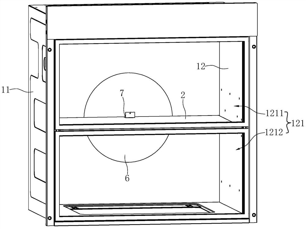
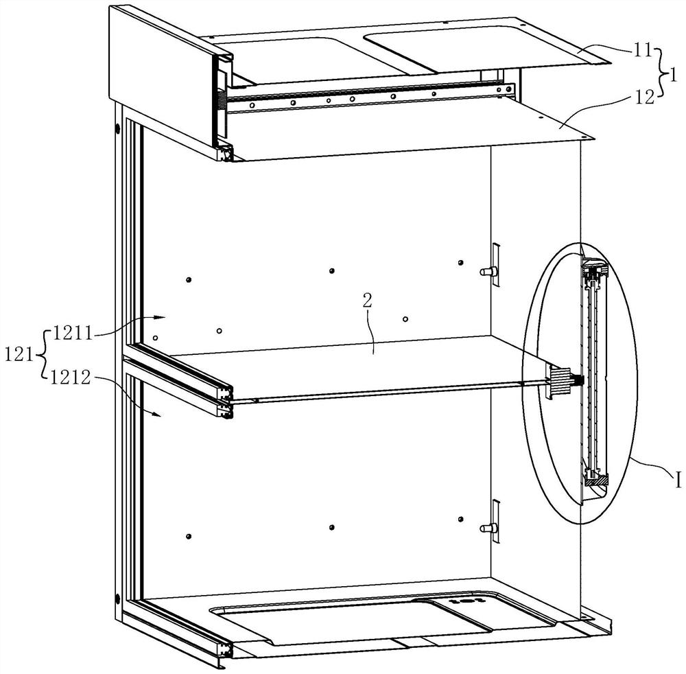
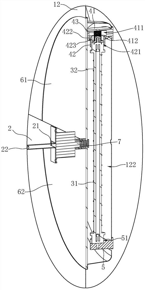
[0040] Such as Figure 1 to Figure 7 Shown is the first preferred embodiment of the layered disinfection cabinet of the present invention. The layered disinfection cabinet includes a cabinet body 1 , a partition plate 2 , a lamp tube 3 , a first lamp holder 4 , a second lamp holder 5 , a light filter cover 6 and a first driving member 7 .

[0041] Wherein, the cabinet body 1 includes an outer shell 11 and an inner tank 12 arranged in the outer shell 11. The inner tank 12 has a disinfection chamber 121, and the rear side wall of the inner tank 12 is partially recessed outward to form a recessed portion 122. The opening of the recessed portion 122 is marked as the first installation opening 1221 .

[0042] The partition plate 2 is arranged substantially horizontally in the middle of the disinfection chamber 121 , and divides the disinfection chamber 121 into a first chamber 1211 located above and a second chamber 1212 located below. The rear part of the partition plate 2 is pr...

Embodiment 2

[0057] Such as Figure 7 to Figure 9 Shown is the second preferred embodiment of the layered disinfection cabinet of the present invention. The difference with Example 1 is:

[0058] In this embodiment, a beam splitter 8 and a second driving member 9 are added.

[0059] Wherein, the reflector 8 is located in the above-mentioned recessed portion 122 , and the above-mentioned lamp tube 3 is located between the light filter cover 6 and the reflector 8 arranged side by side. In this embodiment, the side wall of the side wall of the reflector 8 facing away from the lamp tube 3 is partially pressed inward to form a plurality of bosses 81 arranged at intervals. The direction of the lamp tube 3 gradually decreases, and the side wall of the side wall of the reflector 8 facing the lamp tube 3 is partially pressed outward to form a plurality of grooves 82 arranged at intervals. It gradually decreases toward the direction of the lamp tube 3, thereby diffusely reflecting the pulse flash...


PUM


Abstract

The invention discloses a layered disinfection cabinet. The layered disinfection cabinet comprises an inner container (12), a partition plate (2), a light filtering cover (6) and a lamp tube (3); theinner container (12) is internally provided with a disinfection cavity (121), and provided with a first installation opening (1221); the partition plate (2) is arranged in the disinfection cavity (121); the light filtering cover (6) covers the first installation opening (1221); the lamp tube (3) is arranged outside the light filtering cover (6), wherein the light filtering cover (6) comprises a first light filtering part (61) and a second light filtering part (62), the wall surfaces of which can filter light with different wavelengths respectively; and the light filtering cover (6) can rotaterelative to the lamp tube (3) and has at least two states, so that the first light filtering part (61) and the second light filtering part (62) are respectively positioned on paths where pulse flash acts on the corresponding cavity. Compared with the prior art, two adjacent layers of the layered disinfection cabinet in the invention share the same disinfection device; and meanwhile, various layerscan realize different disinfection modes and can switch the disinfection modes.

Description

technical field [0001] The invention relates to the technical field of kitchen equipment, in particular to a layered disinfection cabinet. Background technique [0002] In the existing layered disinfection cabinet, generally the upper layer is ultraviolet and medium and low temperature disinfection, and the lower layer is high temperature disinfection. [0003] For example, the utility model patent "a double-layer sterilization and disinfection cabinet" with the patent application number CN200820009538.9 (the announcement number is CN201197816Y) discloses a double-layer sterilization and disinfection cabinet, including a cabinet body, a disinfection inner cavity, a cabinet door, And the control circuit, there are 2 disinfection inner chambers, one of which is equipped with a sterilization device that can generate ozone and / or ultraviolet rays, and the other disinfection inner chamber is equipped with 2 or more disinfection devices according to the scope of sterilization The...

Claims


Application Information

Patent Timeline
Patent Type & Authority Applications(China)
IPC IPC(8): A61L2/08A61L2/10A61L2/26
CPCA61L2/08A61L2/10A61L2/26A61L2202/23
Inventor 张文龙吴再锐王军元
Owner NINGBO FOTILE KITCHEN WARE CO LTD
Why Eureka
Try Eureka