A nuclear radiation-resistant mobile cable for cranes
A nuclear radiation-resistant and mobile cable technology, which is applied in the field of cables, can solve the problems that easily affect the erection of construction supports, the large footprint of flat cables, and affect the safety of use, so as to achieve a small footprint, reduce the impact of erection, and alleviate wear effect
- Summary
- Abstract
- Description
- Claims
- Application Information
AI Technical Summary
Problems solved by technology
Method used
Image
Examples
Embodiment 1
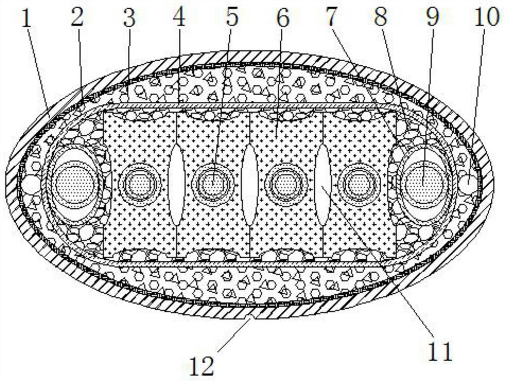
[0028] like figure 1 The shown mobile cable with resistance to nuclear radiation for cranes includes a cable core, an insulating layer 4 wrapped around the cable core, an armoring layer 2 arranged on the outside of the insulating layer 4, and a cable wrapped on the outside of the armoring layer 2. The sheath layer 1, the cable core includes a main wire core 5 and a ground wire core 9;
[0029] The cross-sections of the armoring layer 2 and the sheathing layer 1 are both oval, and the sheathing layer 1 is made of irradiated cross-linked polyethylene material. The wear-resistant groove 12 extends in the length direction, and the groove surface in the wear-resistant groove 12 is sprayed with wear-resistant paint; the armor layer 2 is a tube-sleeve-shaped structure woven from copper tape;
[0030] The cross-section of the insulating layer 4 is flat, and the two sides thereof are convex arcs, the insulating layer 4 is an irradiated cross-linked polyethylene insulating layer; Ther...
Embodiment 2
[0035] The difference between this embodiment and Embodiment 1 is:
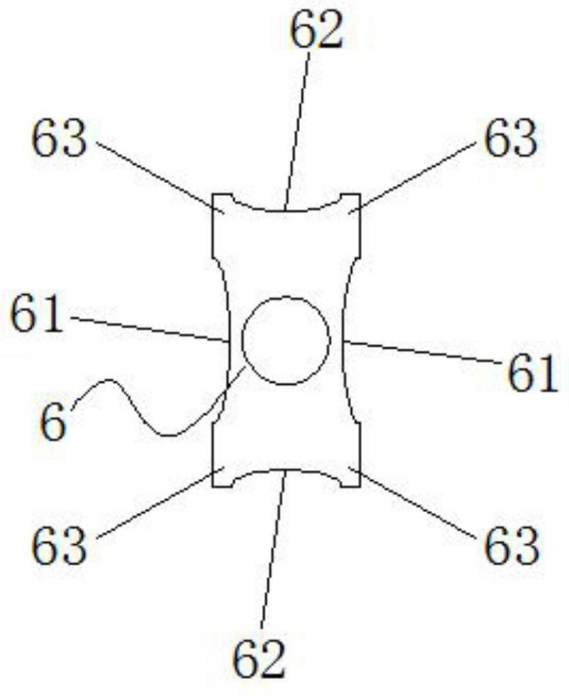
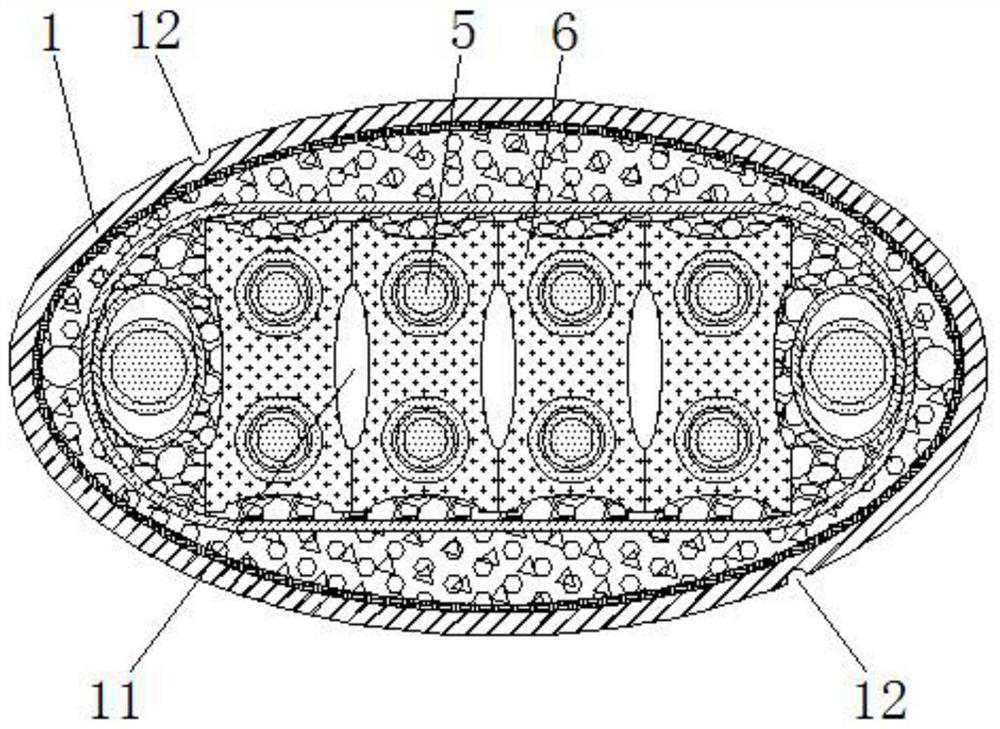
[0036] In this embodiment, as image 3 As shown, there are a row of first protective sleeves 6 attached to each other in the cable core, and two main wire cores 5 are arranged inside each first protective sleeve 6, and each adjacent two first protective sleeves 6 face each other. The side first arc grooves 61 are pieced together to form an oval cavity 11 . The arrangement of more main cores 5 can be realized.
[0037] In this embodiment, as image 3 As shown, there are two wear-resistant grooves 12 extending along the length direction of the outer surface of the sheath layer 1 , and the two wear-resistant grooves 12 are point-symmetrical about the center of the section of the cable.
[0038] Others are the same as in Example 1.
Embodiment 3
[0040] The difference between this embodiment and Embodiment 1 is:
[0041] In this embodiment, as Figure 4 and Figure 5 As shown, there are two rows of first protective sleeves 6 attached one by one in the cable core, and the bottom of the first protective sleeve 6 of the upper row and the top of the first protective sleeve 6 of the next row are attached together, There is a main wire core 5 on the inner side of each first protective sleeve 6 , and the first arc grooves 61 on the opposite sides of each adjacent two first protective sleeves 6 are pieced together into an oval cavity 11 . The second arc grooves 62 on the opposite sides of the first protective sleeve 6 are pieced together to form an oval cavity 11 . The arrangement of more main cores 5 can be realized, and the number of cavities 11 can be increased, so that the flexibility of the cable can be improved.
[0042] In this embodiment, as Figure 4 As shown, there are four wear-resistant grooves 12 extending alo...
PUM
 Abstract
Description
Claims
Application Information
 - Generate Ideas
- Intellectual Property
- Life Sciences
- Materials
- Tech Scout
- Unparalleled Data Quality
- Higher Quality Content
- 60% Fewer Hallucinations
Browse by: Latest US Patents, China's latest patents, Technical Efficacy Thesaurus, Application Domain, Technology Topic, Popular Technical Reports.
© 2025 PatSnap. All rights reserved.Legal|Privacy policy|Modern Slavery Act Transparency Statement|Sitemap|About US| Contact US: help@patsnap.com


