Method for detecting prestress of steel strand under bridge anchor
A detection method and prestressing technology, applied in tension measurement, force/torque/work measuring instrument, measurement device, etc., can solve the problems of large error in measurement results, influence of measurement accuracy, poor elastic wave stability, etc. The detection method is simple and efficient, the measurement results are accurate and stable, and the effect of reducing errors
- Summary
- Abstract
- Description
- Claims
- Application Information
AI Technical Summary
Problems solved by technology
Method used
Image
Examples
Embodiment 1
[0058] A method for detecting the prestress of a steel strand under anchorage of a bridge, comprising the steps of:
[0059] Step a1: using the stress wave excitation device and the stress wave receiving device to detect the acoustic characteristics of the anchor head of the prestressed steel strand anchorage, so that the stress wave receiving device receives the acoustic wave signal;
[0060] Step a2: processing the acoustic wave signal in step a1 to obtain a spectrogram of the acoustic wave signal;
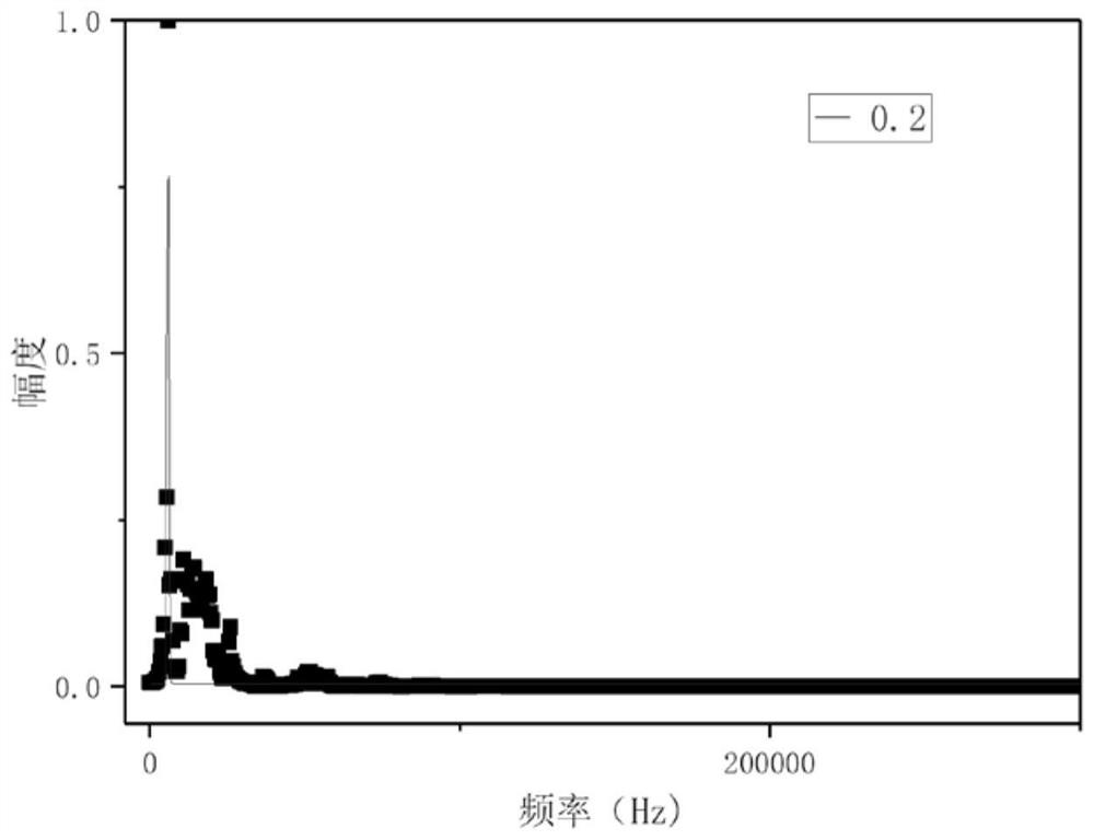
[0061] Step a3: Fit the logarithmic normal distribution to the spectrogram in step a2 to obtain the logarithmic standard deviation σ of the fitted curve;
[0062] Step a4: Substitute the logarithmic standard deviation σ of step a3 into the formula: σ t =[0.867+0.113ln(σ-0.044)]*1860, get the prestress σ of the steel strand to be tested t ;
[0063] Step a5: The prestress σ obtained in step a4 t Compared with the prestressed design value m of the steel strand:
[0064] If σ ...
Embodiment 2
[0097] Different from Embodiment 1, in Embodiment 2, step a4 obtains the formula σ through simulation software t =[0.867+0.113ln(σ-0.044)]*1860.
[0098] Step a4 includes the following steps:
[0099] Step a'41: Establish the finite element models of the prestressed steel strands in multiple groups of different prestresses respectively in the simulation software;
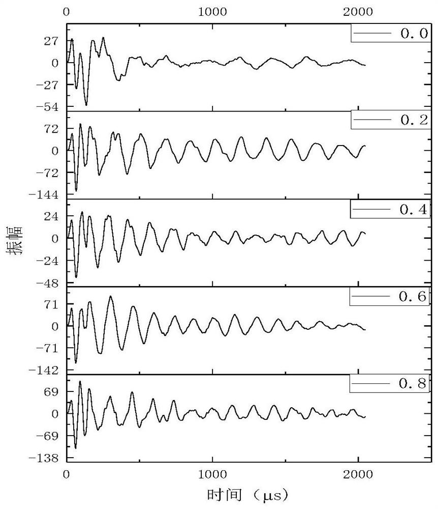
[0100] Step a'42: If Figure 5 As shown, in each finite element model, the first measuring point A on the side of the anchor head in each finite element model excites low-frequency stress waves, and the second measuring point B on the opposite side of the first measuring point A receives the stress wave transmission signal. acoustic signal, such as Figure 6 shown.
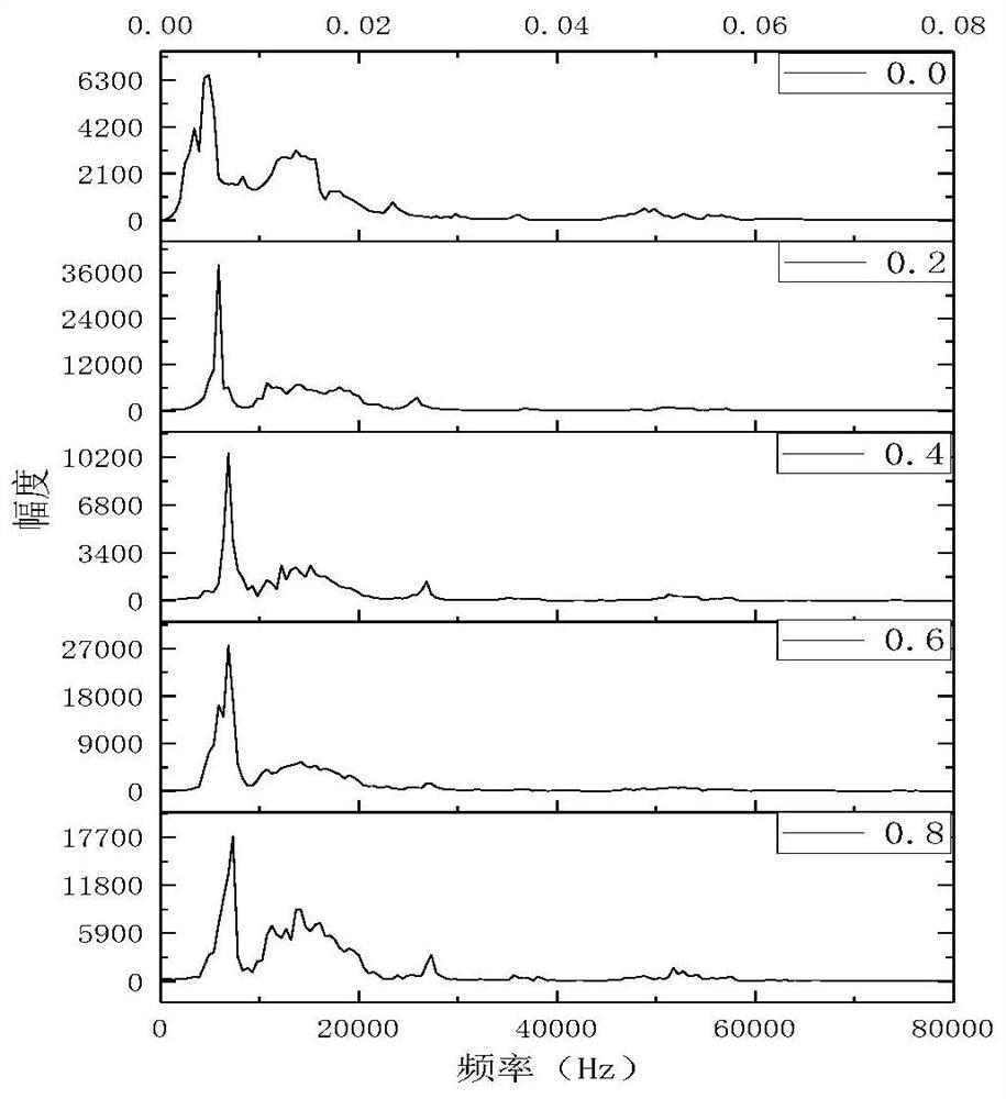
[0101] Step a'43: process the multiple groups of sound wave signals obtained in step a'42 to obtain the spectrum diagrams of multiple groups of sound wave signals, such as Figure 7 shown;
[0102] Step a'44: Fit the logarithmic normal distributio...
PUM
| Property | Measurement | Unit |
|---|---|---|
| Diameter | aaaaa | aaaaa |
| Tensile strength | aaaaa | aaaaa |
Abstract
Description
Claims
Application Information
 - R&D Engineer
- R&D Manager
- IP Professional
- Industry Leading Data Capabilities
- Powerful AI technology
- Patent DNA Extraction
Browse by: Latest US Patents, China's latest patents, Technical Efficacy Thesaurus, Application Domain, Technology Topic, Popular Technical Reports.
© 2024 PatSnap. All rights reserved.Legal|Privacy policy|Modern Slavery Act Transparency Statement|Sitemap|About US| Contact US: help@patsnap.com


